

This section describes the essential basics for understanding mechanics.

Vector sizes in cross-section
A vector is a directed quantity. Unlike a scalar quantity, which is described by a number (for example, a temperature), a vector is described by a direction and a magnitude (for example, a force).
Moments and lateral forces that occur at one point in a cross-section can be described as a 3D vector. Since the permissible values are usually specified in relation to the axes of the cross-section, the components of the 3D vector are displayed in the software in the cross-section coordinate system (see graphic).
External forces are action forces (attached loads, dead weight, impressed pre-deformations) and reaction forces caused by them (bearing forces, suspended point loads).
Action forces from weights generally correspond to the mass multiplied by the acceleration it experiences. For static systems in event technology, the force usually corresponds to the mass multiplied by the acceleration of gravity.
Pre-deformations or imperfections are differences between the ideal geometry and the actually installed component. They can lead to action forces in statically undetermined systems.
External moments as forces of action occur in event technology, for example, as offset moments when loads are not inserted above the centerline of a traverse. As reaction forces in the suspension points of a system, moments usually do not occur in hanging systems, since ropes and chains cannot initiate moments in anchor points.
Internal forces arise within a cross-section in response to external forces between force input and dissipation. In special cases, internal forces can also occur without external forces, for example in the case of deformations of cross-sectional parts against each other.
A distinction is made between normal forces (Nx), transverse forces (Vy, Vz), torsional moments (Mt) and bending moments (Mby, Mbz).

Vector sizes in cross-section - forces
The unit of force is the Newton ( N = [ kg * m / s2 ], for example 9,81N = 10kg * 9,81 m/s2).
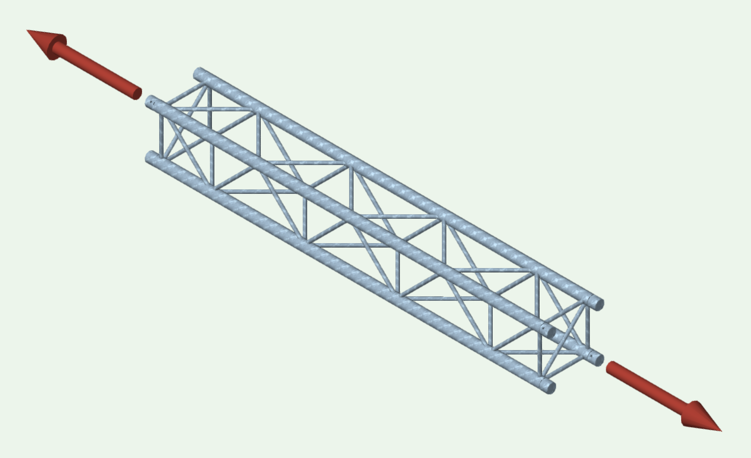
Normal forces pull a cross-section apart (as in the picture above) or push it together. A beam under pressure can buckle depending on its length (stability problem). In the case of a hanging systems in event technology, this effect usually does not occur.
Pure normal force leads to uniform tensile or compressive forces in the belts.
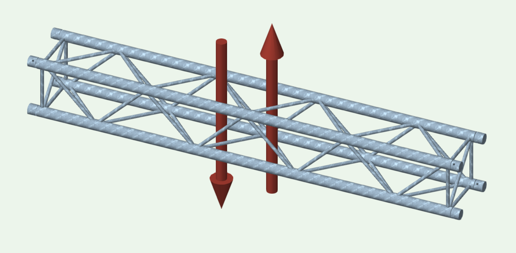
Transverse forces shift a cross-section transversely to the longitudinal axis. In the picture above, the truss would be sheared between the forces.
Pure transverse forces lead to forces in the bracing rods of a truss.

Vector sizes in cross-section - moments
Moments are pairs of forces. They are equivalent to two parallel, opposing forces with a lever arm.
The unit is newton meters ( Nm = [ kg * m2 / s2 ] ).
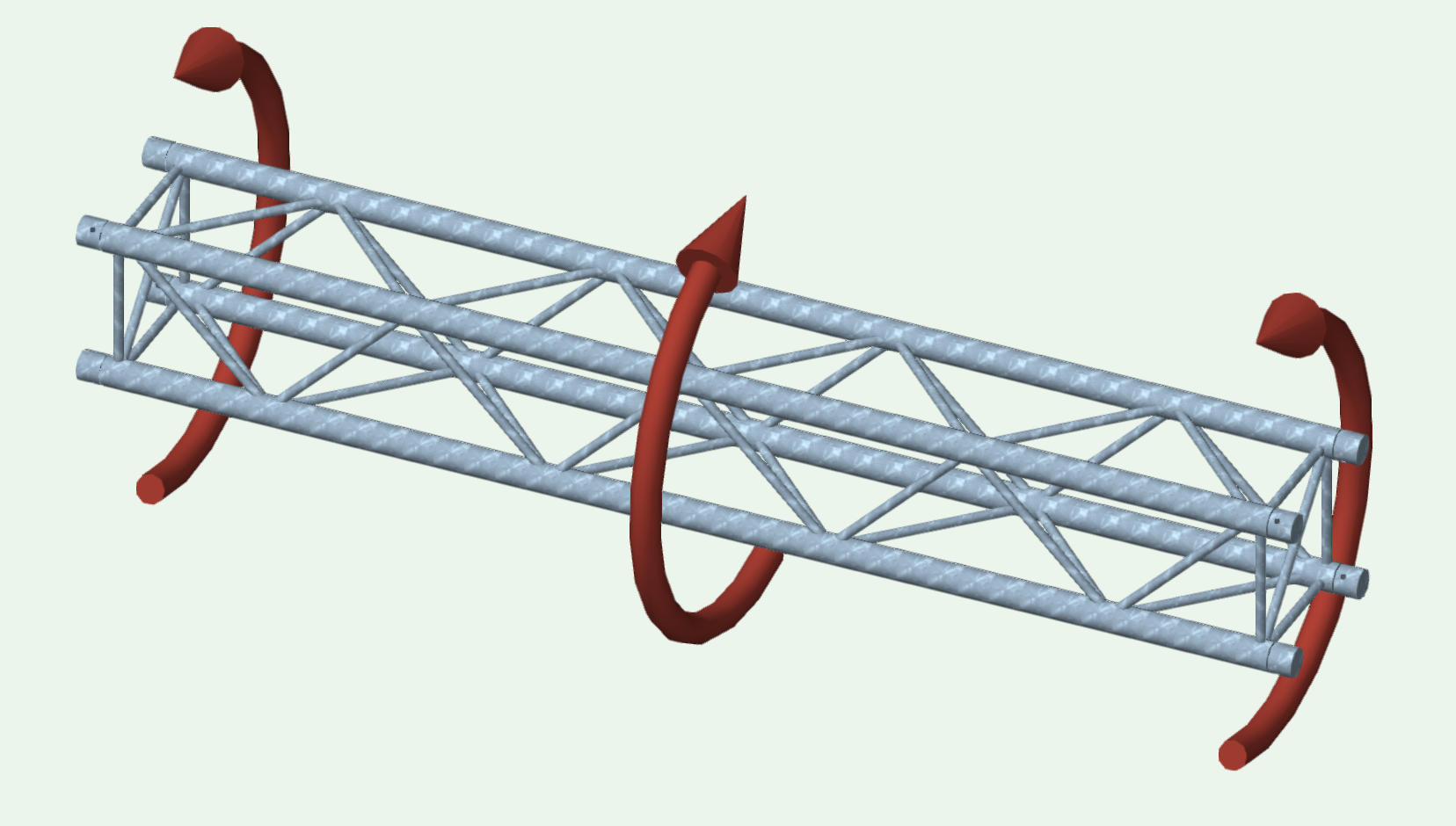
Torsional moments twist a cross-section along its longitudinal axis. In event technology, they occur, for example, in the case of outriggers or truss frames, in which bending moments are introduced via rigid connections as torsional moments onto transverse trusses if they cannot twist freely.
Pure torsion prematurely leads to forces in the bracings and in the case of an alternating bracing procedure, to additional forces in the belt tubes.
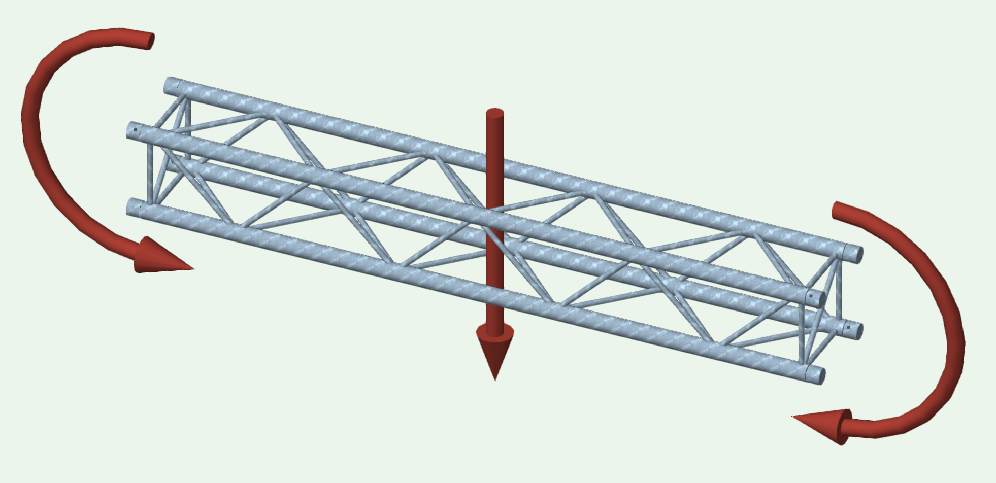
Bending moments are usually the determining factor in the design of trusses. They bend a cross-section against its ideal cross-sectional line and thus lead to the characteristic deformation.
Pure bending leads to forces in the belt tubes. If a truss bends downwards, compressive forces act in the upper belt tubes and tensile forces in the lower belt tubes.

Vector sizes in cross-section - deformations
Deformation describes displacement and twisting against the ideal cross-sectional line.
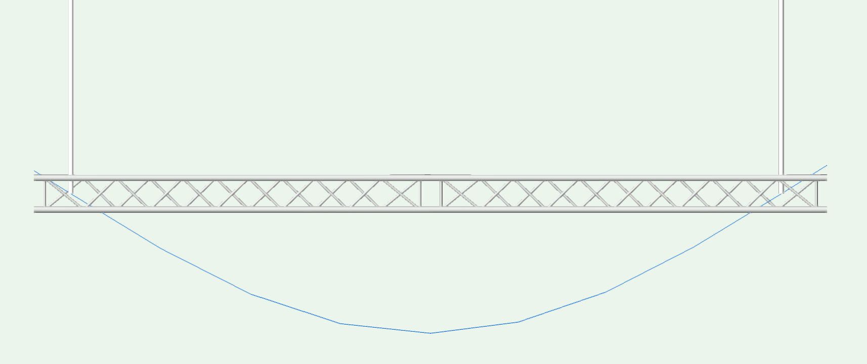
Example deformation curve - the blue line shows the deflection of the truss by its own weight.
Technical mechanics essentially deals with the effect of forces on and in solids ("solid mechanics"). It is divided into three large sub-areas.
Statics deals with forces on stationary, rigid solids. In pure statics, all bodies are infinitely stiff.
By the means of statics, bearing loads can be clearly determined by the balance of forces in statically determined supported systems. (see =>Statically determined systems below).
If the length of a solid is significantly greater than its width and height, it is called a "beam".
From action and reaction forces, the internal forces or influence lines can be determined for beams.
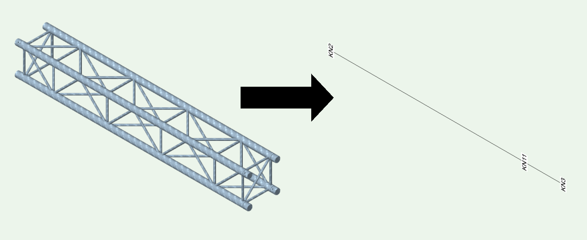
Abstraction of a traverse as a bar
Trusses are abstracted as a bar in the FEM model. In the cross-sectional analysis, the calculated influence lines of the beam are again related to the truss geometry.
Statics forms the basis for strength of materials and dynamics.
The strength of materials deals with forces and deformations on still (unmoved) bodies. According to strength of materials, a body has specific stiffness properties that are composed of cross-sectional geometry and material characteristics.
Based on the stiffness properties, stresses and resulting deformations can be determined.
The knowledge of the laws of deformation extends the calculable systems by the statically undetermined supported systems, in which the bearing forces depend on the stiffness of the system.
Kinematics deals with accelerated or moving points or solids without consideration of forces and masses. In kinematics, the differential relationship between acceleration, speed and position (or angular acceleration, angular velocity, angle) is dealt with.
Kinetics deals with accelerated or moving solids under the influence of forces. By means of impulse theorem, energy theorem or working theorem, the acceleration of the masses resulting from the acting forces can be determined.