

In this tutorial, we will create an Aluvision Booth in SketchUp, calculate the stability analysis with Production Assist, and export the results as a PDF.
Before you start this tutorial, make sure you have the following:
Time required: Approx. 30-45 minutes
The following information will be determined:
Additionally, there is the option to have the booth checked by our engineering office. This creates a verifiable static calculation that can be submitted to the authorities. You can find more information about this here.
To create the Aluvision booth in SketchUp, you need to install the Aluvision extension. You can find it in the SketchUp Extension Warehouse.
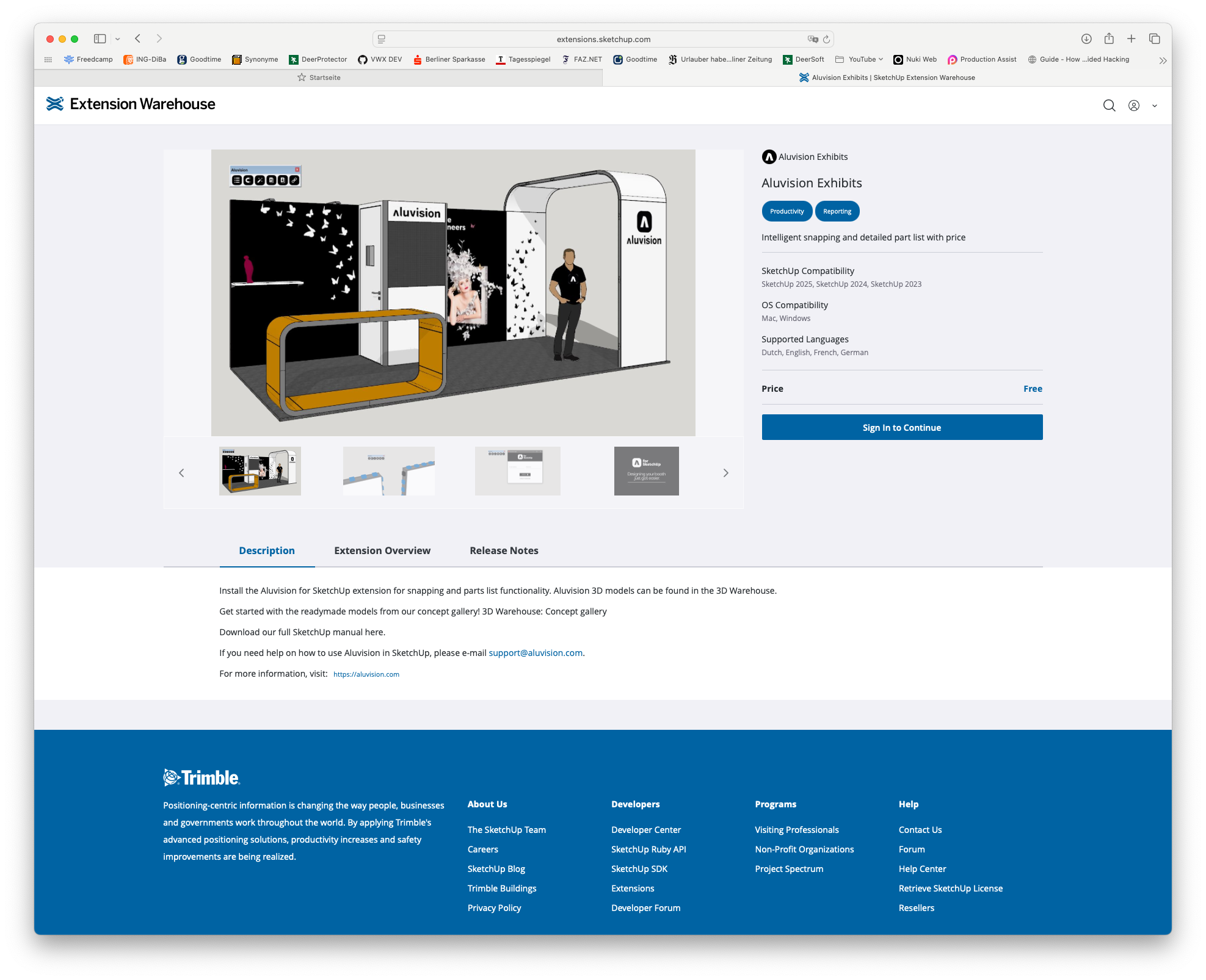
This extension offers the ability to draw Aluvision profiles directly in SketchUp. There is a library with various profiles that are directly prepared to perform static calculations with Production Assist.
An introduction to the Aluvision extension can be found in the video documentation on Vimeo.
For the rest of this tutorial, we assume that you have already installed the Aluvision extension and are familiar with its operation. If you have questions about using the Aluvision extension, feel free to contact Aluvision support or read the documentation on the extension's website.
Now select the desired Aluvision profile from the library and import it into your drawing.
| Library Overview in 3D Warehouse | Detail Page of 3D Warehouse |
|---|---|
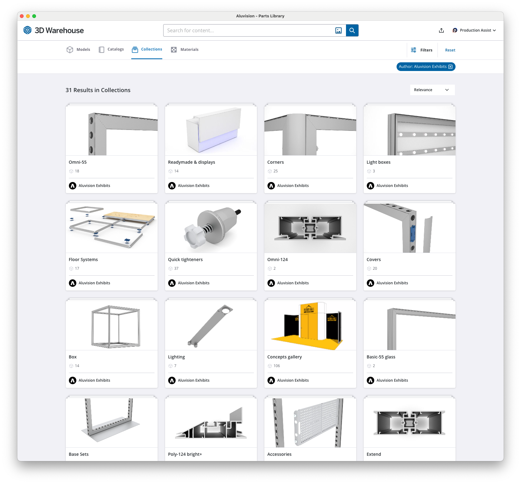 | 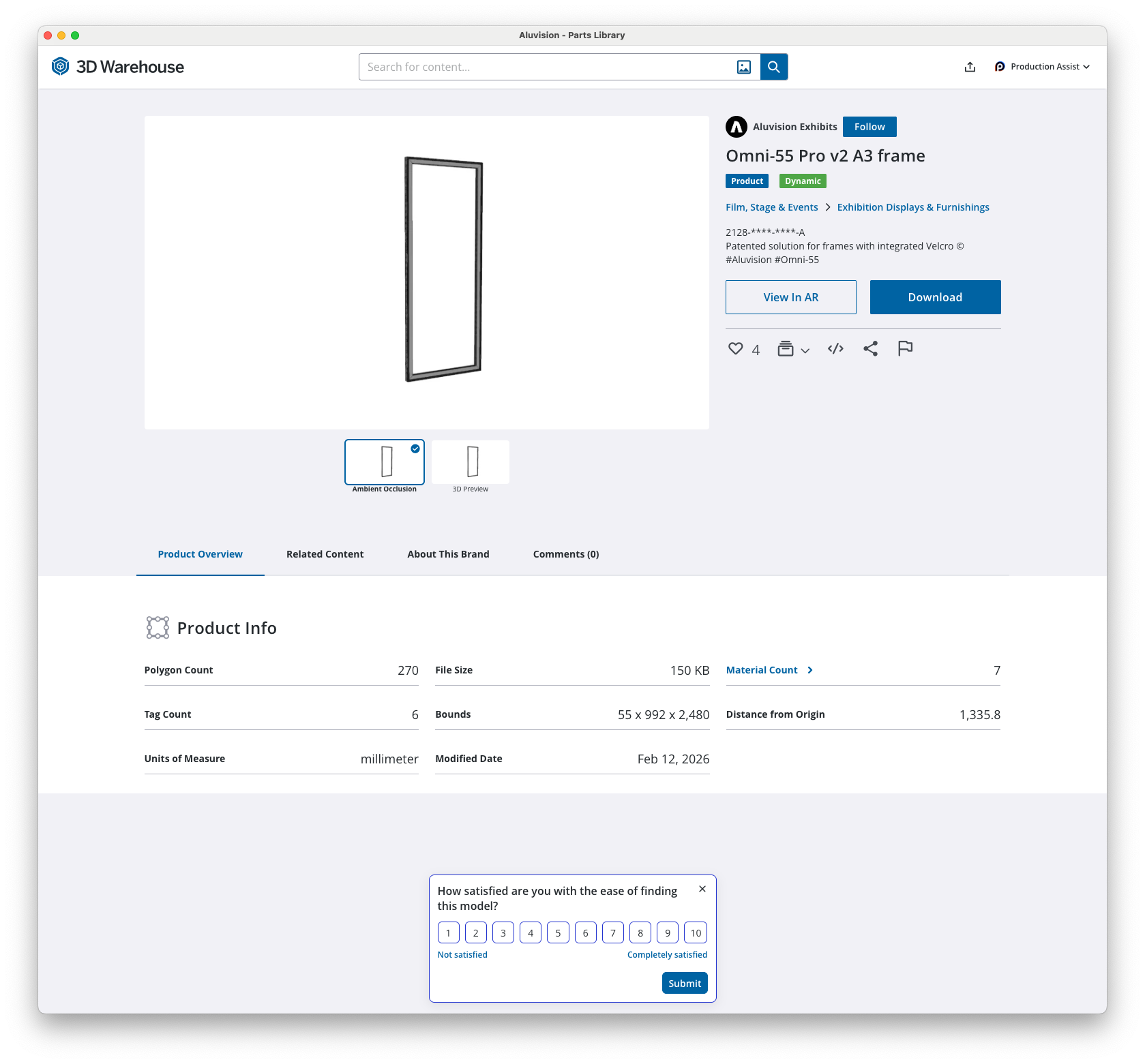 |
After importing the profile into your drawing, you can now duplicate the profile and draw the various parts of the booth.
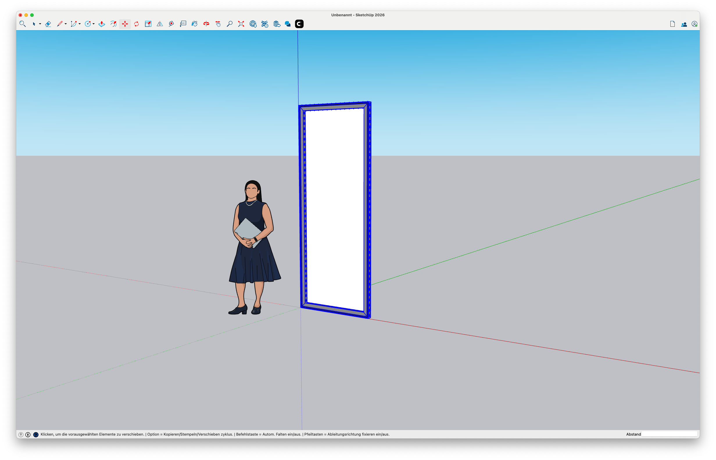
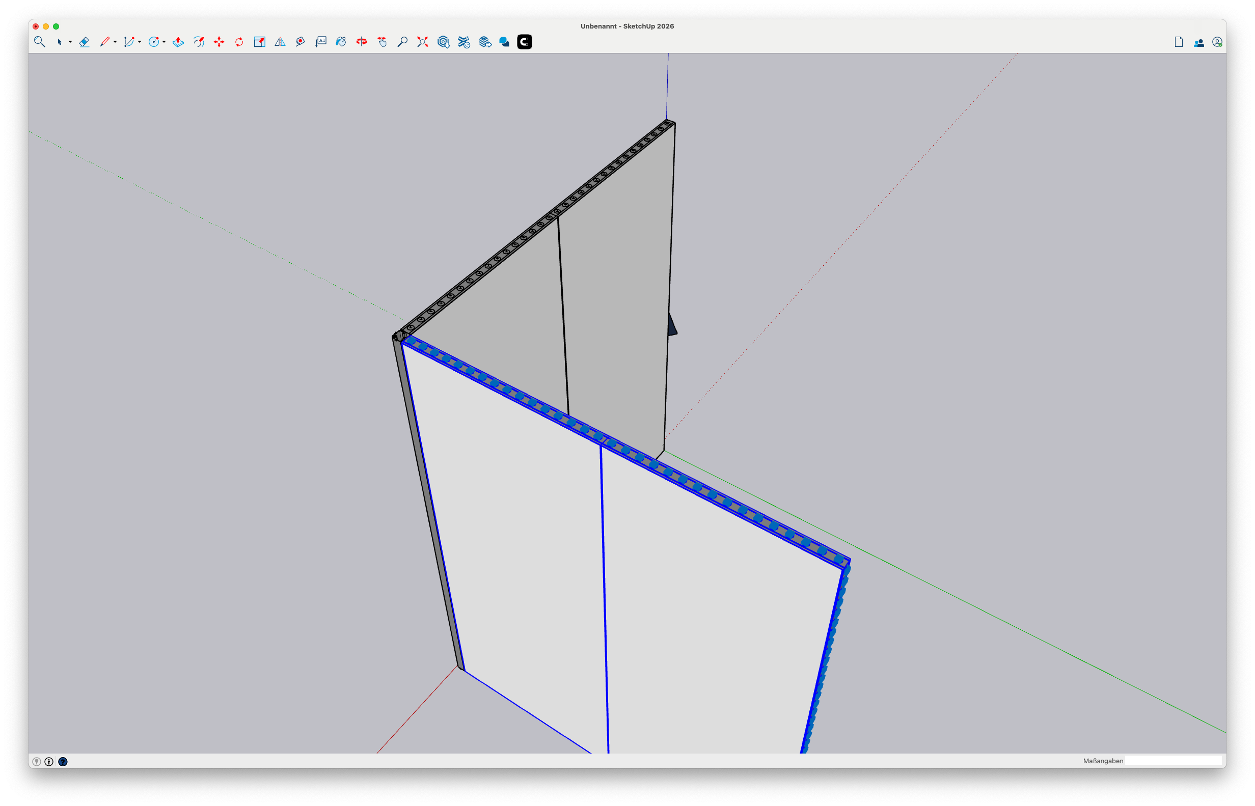
Use the Aluvision snapping tool (automatic snapping to connection points) to connect the profiles with each other. It is important that the profiles are connected to each other so that Production Assist recognizes the profiles as one unit and performs the static calculation correctly. If the profiles are not connected to each other, Production Assist might recognize the profiles as individual elements and not perform the static calculation correctly.
| Specify connection lines for snapping | Connected profiles after snapping |
|---|---|
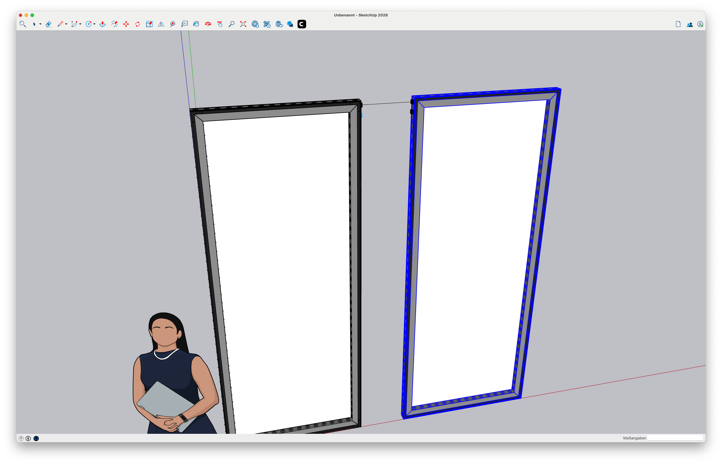 | 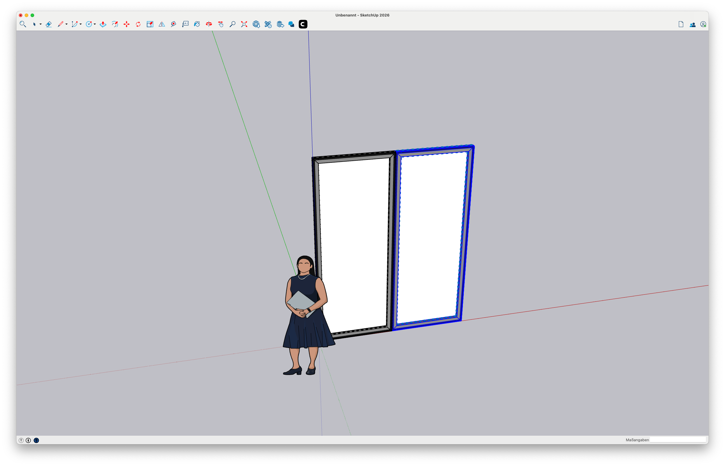 |
Now insert a corner into the drawing so that the profiles are connected to each other. Repeat this step to connect all profiles.
| Insert corner and connect other frames | Connected profiles after snapping |
|---|---|
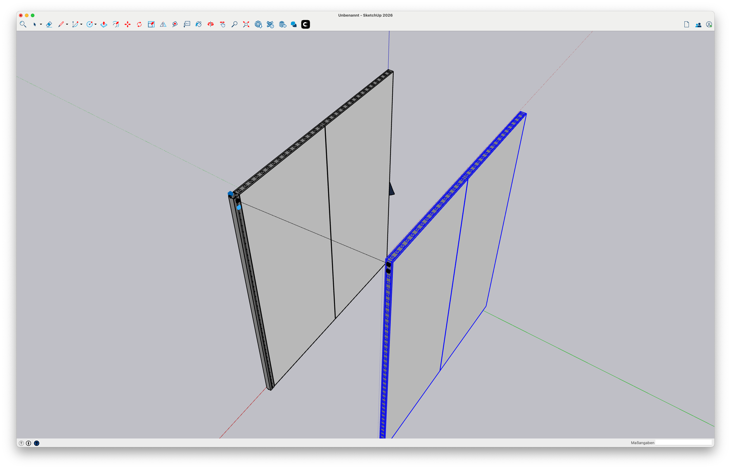 |  |
Repeat these steps until you have a coherent booth. For this tutorial, we created a simple booth with 4 sides and 4 corners.
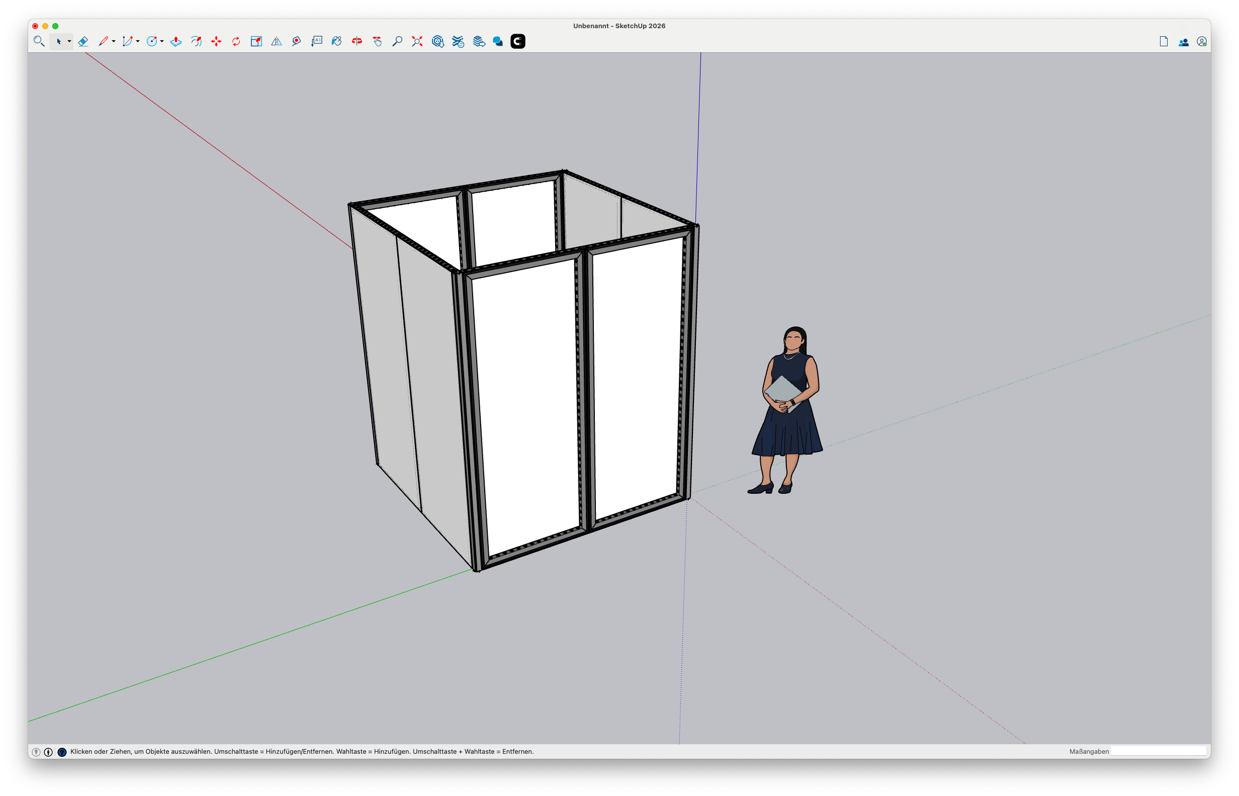
After drawing this, the next step is to insert the connectors. Connectors are the elements that connect the profiles to each other and transfer the loads. It is important that the connectors are positioned correctly so that Production Assist can calculate correctly.
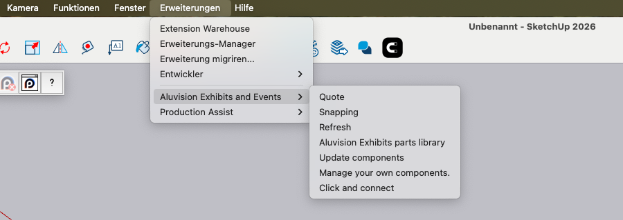
To do this, click on the command Extensions->Aluvision Exhibits and Events->Click and connect. This automatically inserts connectors at the locations where the profiles are connected to each other.
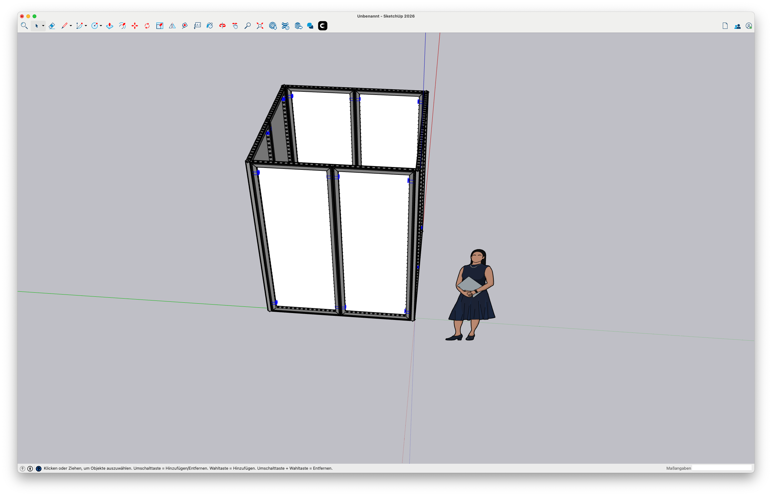
The profiles are now connected with the appropriate connectors. These are marked in blue in this image. If the booth is not drawn cleanly, not all connectors can be inserted.
Note: If not all connectors are inserted automatically:
Now open the Production Assist UI in SketchUp via the button
 in the Production Assist toolbar. The Production Assist window will open on the right side in SketchUp.
Then start the synchronization with Production Assist via the button
 in the Production Assist toolbar. Now the data from SketchUp will be sent to Production Assist.
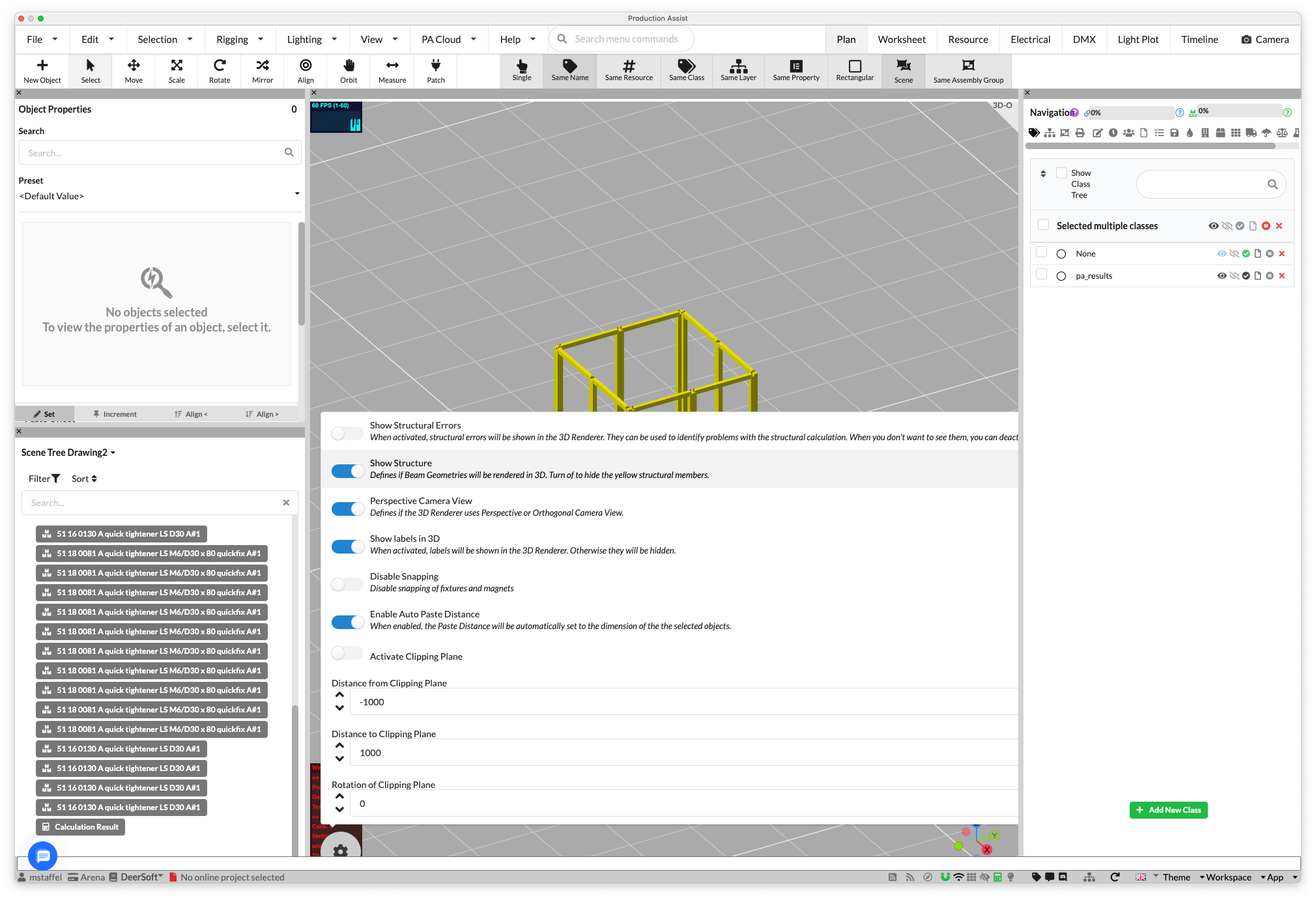
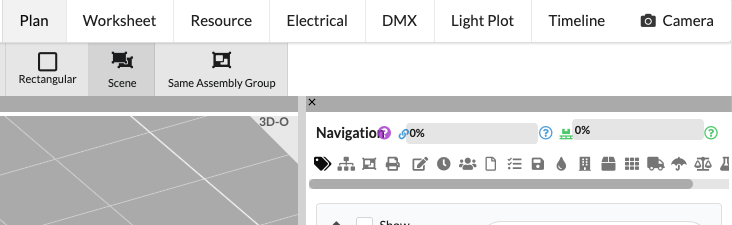
In the top right, click on the Plan view to see the booth in 3D in Production Assist as well. Also make sure that Show Structures is enabled in the Quick Settings so that the structures are visible in the 3D view. To do this, click on the gear button in the 3D view and enable the Show Structures option.
Note: The 3D geometry from SketchUp is not sent to Production Assist, only the structural elements. If Show Structures is not enabled, no structures will be displayed in the 3D view.
| Enable Show Structures | Display of booth in 3D |
|---|---|
 | 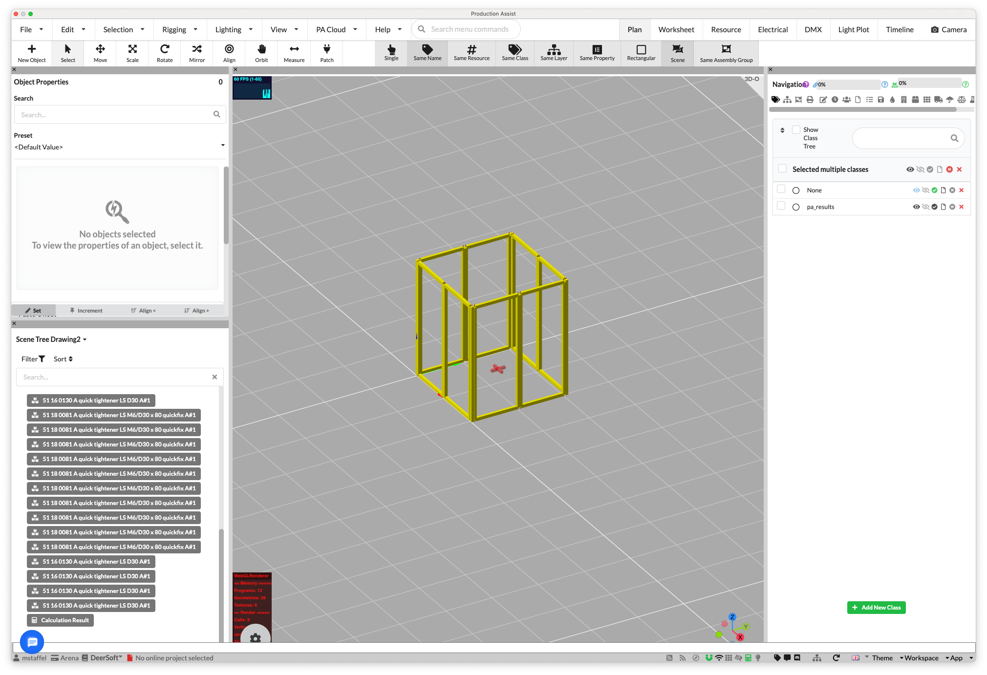 |
Now the frames and connectors are visible in Production Assist. However, Production Assist cannot calculate yet because no supports are defined. You can see this from the gray utilization indicator in the top right of the navigation.
To insert the supports, we will set up Production Assist to automatically insert supports at the floor level.
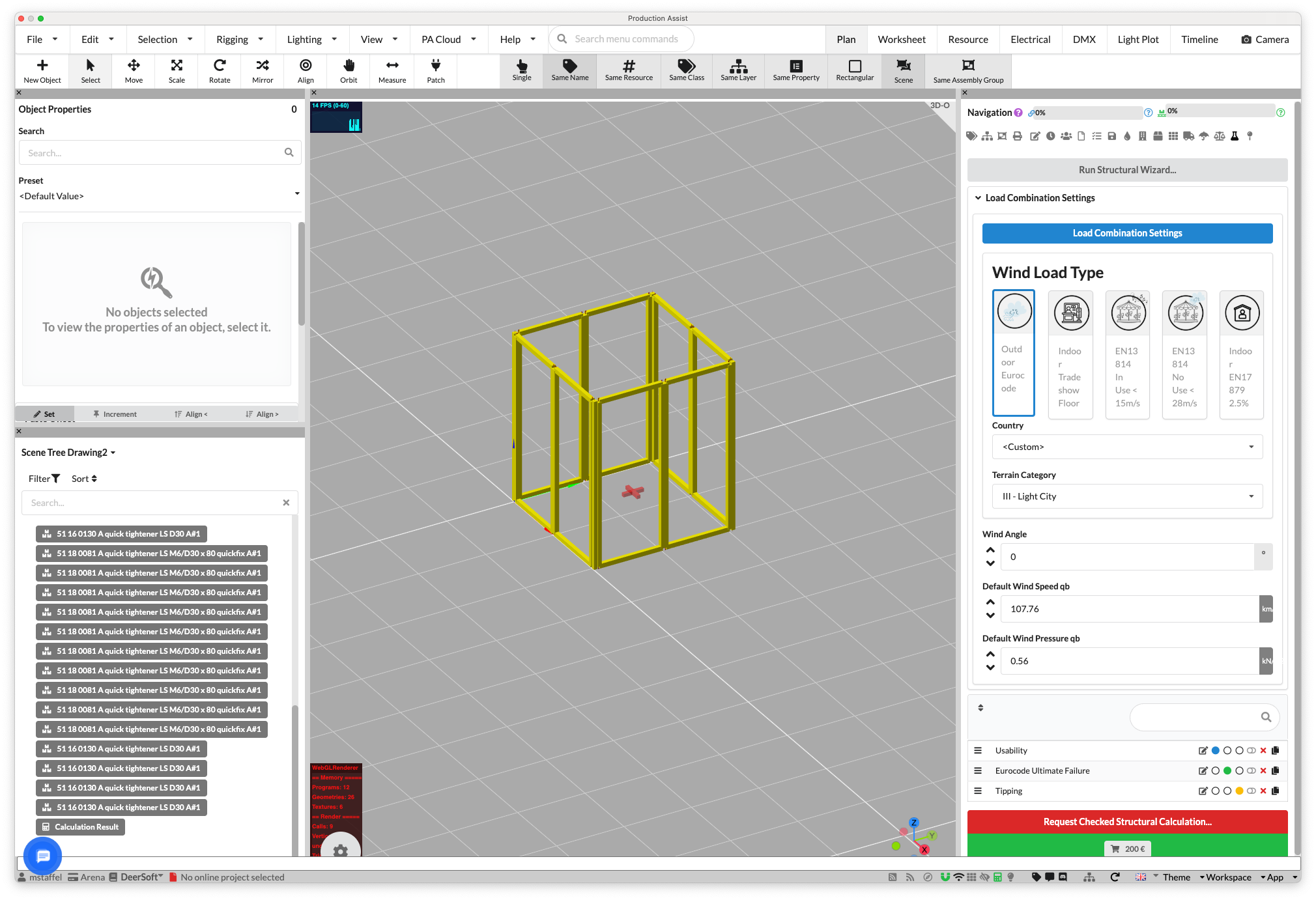
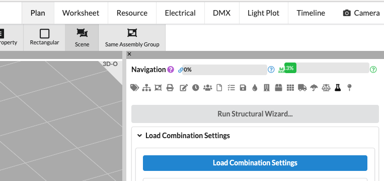
To do this, click on Load Combinations in the navigation and then on Load Combinations Settings. Now enable the option Automatically add supports at the bottom of the structure.
| Load Combinations Settings | Enable use floor as support |
|---|---|
 | 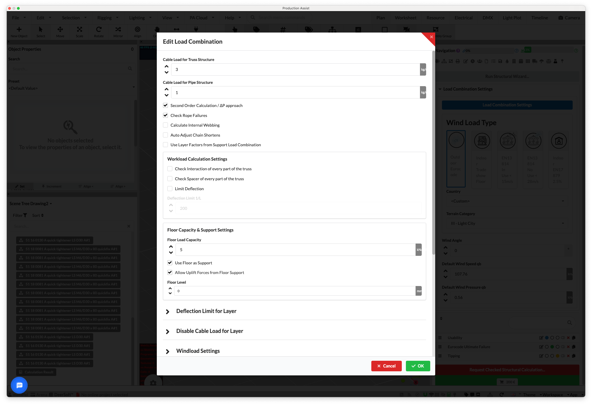 |
The calculation will now start automatically because the supports are now defined. Now you can see the results of the calculation in the overview.
| Load Combinations Settings | Booth with enabled supports |
|---|---|
|  |
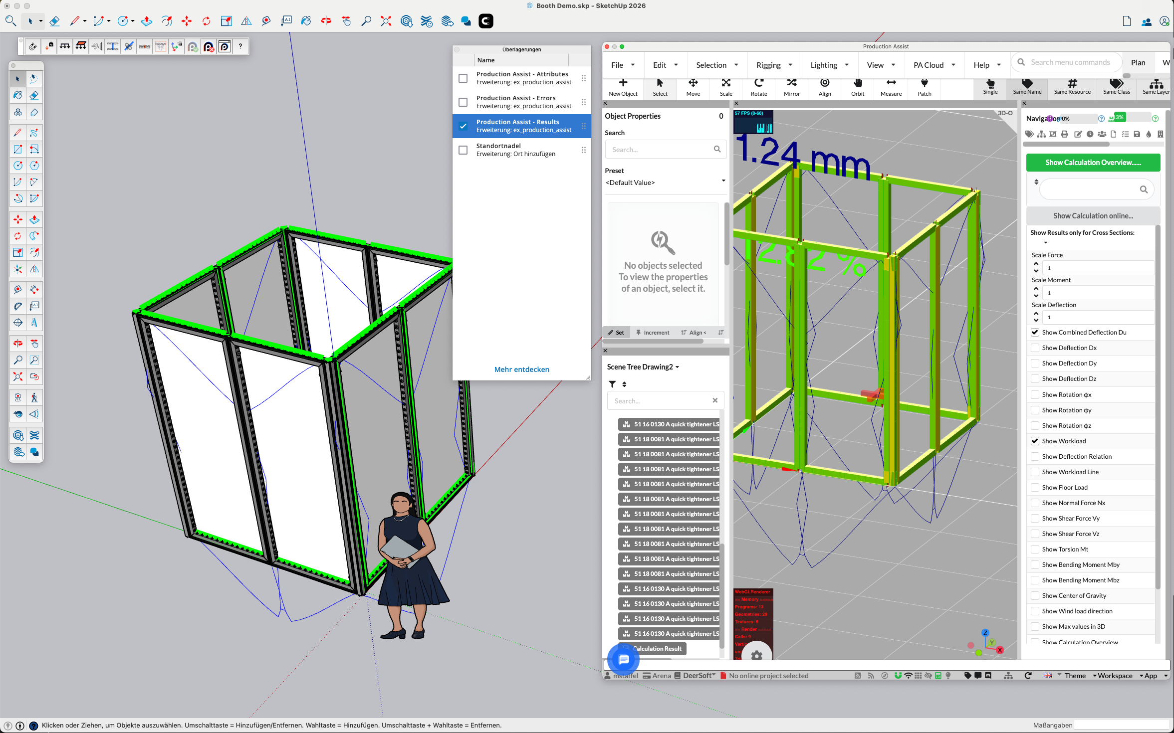
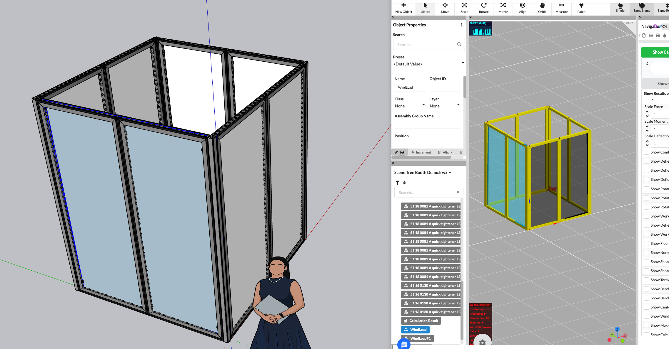
Production Assist can now calculate. To see the results of the calculation, click on Section Reaction in the navigation (here you see the forces and loads at the connection points). Here you can now see the utilization of the frames and connectors.
If you also select Utilization and Deflection, they will be displayed in the 3D view. Via the Overlays, this information can now also be displayed directly in the SketchUp drawing area. To do this, enable the Show Load Overlay option.
Now we need to insert the horizontal loads to see the effects on the structure. For this tutorial, we will assume that the hall wind is 0.125 kN/m² up to 4m and above 4m 0.06 kN/m². This corresponds to the technical rules for trade shows in Germany and Spain.
To do this, we will insert two wind surfaces into the drawing. Click on the Add Wind Surface button in the Production Assist toolbar.

Then draw the area of one side of the booth. The cursor automatically snaps to the frames so that the area is exactly on the side of the booth. You finish entering the area with a double-click. Repeat this step for the other side of the booth.
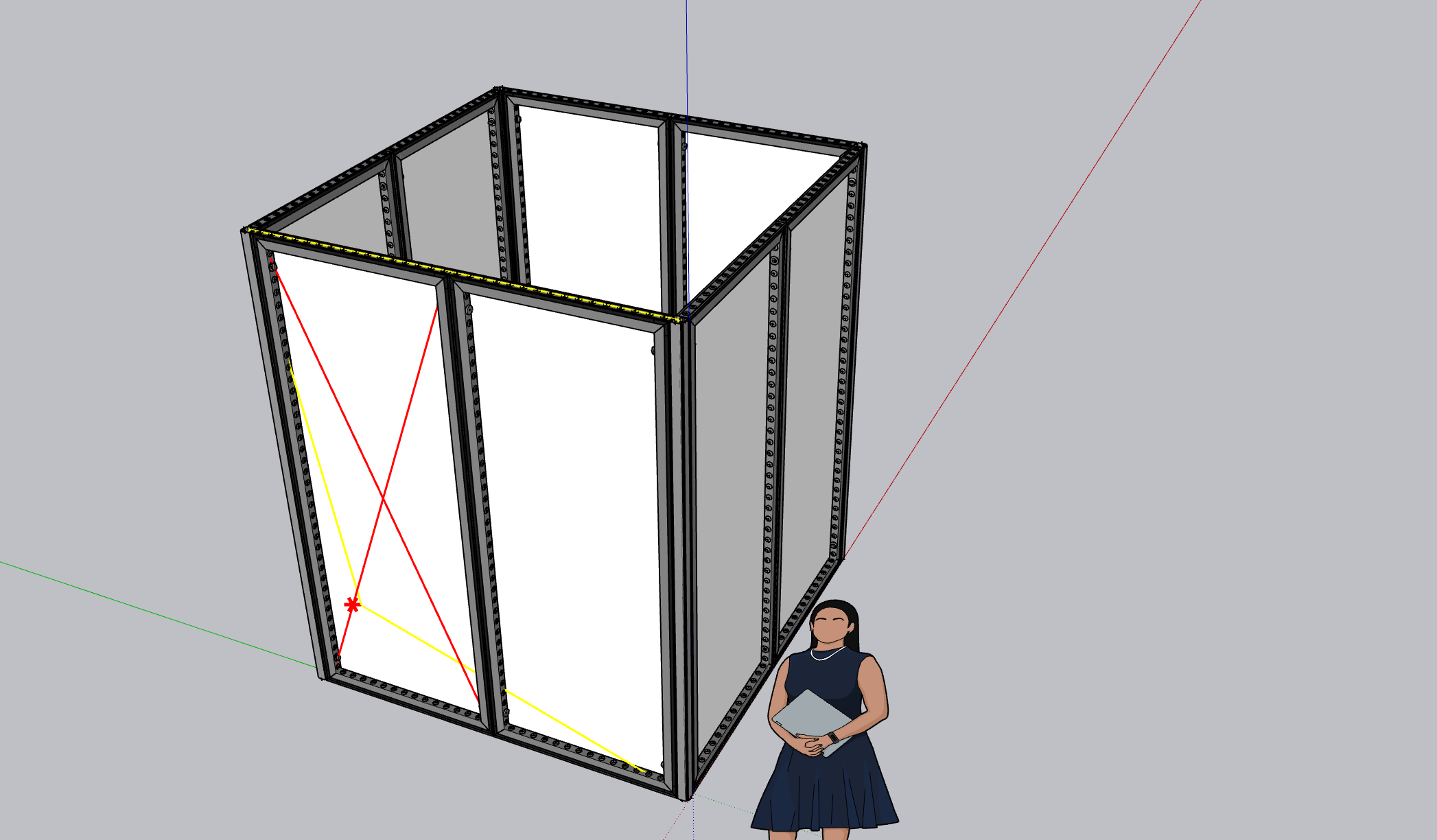
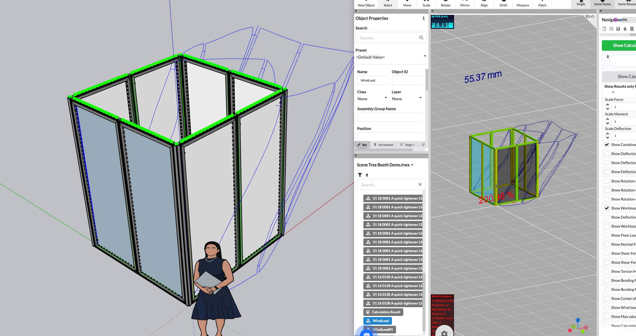
When the surfaces are drawn, they will be displayed in SketchUp and Production Assist.
If you now look at the utilization of the frames and connectors, you will see that the load from the wind loads has increased significantly. By default, Production Assist calculates with the wind values for outdoor applications. Therefore, the deflection and utilization of the frames are now significantly higher than before.
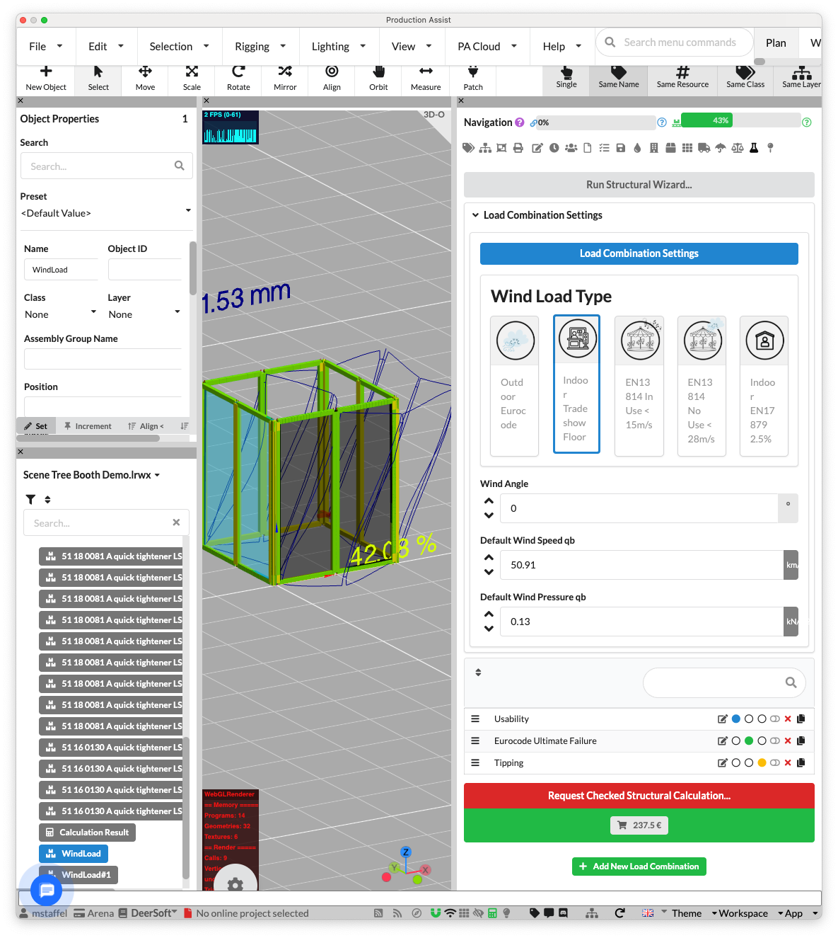
To use the wind loads for indoor applications, you need to adjust the wind loads in the load combinations. To do this, click on Load Combinations in the navigation and then on the Indoor Tradeshow Floor button. Now the wind loads for indoor applications will be used and the load on the frames and connectors is significantly lower than before.
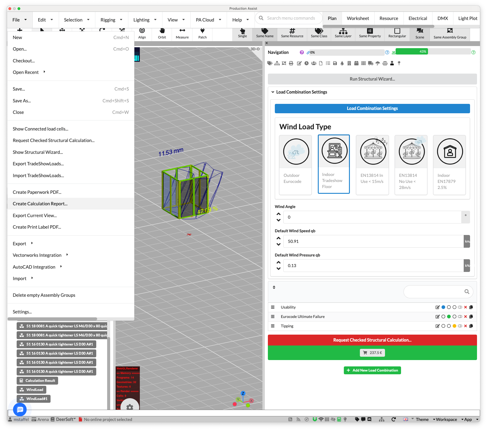
This completes the calculation of the booth. Now we can export the results to submit them to the authorities or send them to the customer, for example.
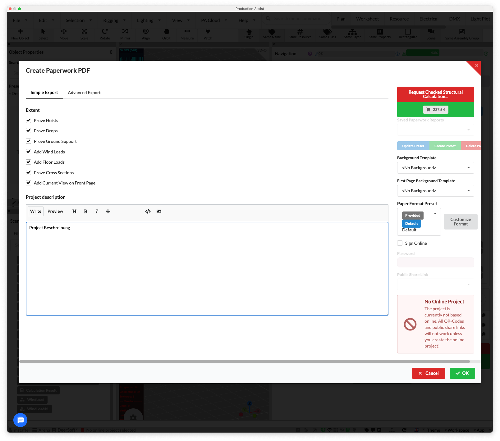
In the menu bar, click on the button File->Create Calculation Report.
Now a dialog opens where you can select the information to be included in the report. Select the information you want in the report and then click on the Export Report button.
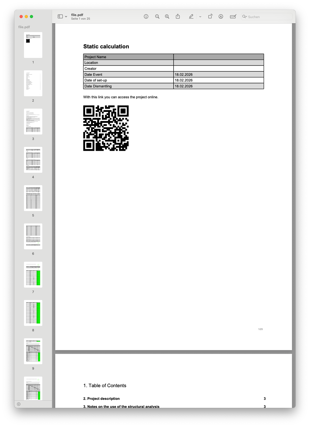
Congratulations! You have now created a PDF report with the results of the static calculation of your Aluvision booth. This report contains the most important information such as the required ballast amount, the number of required screws, and the maximum load on the frames.
If you have questions about this tutorial or encounter problems:
You can find more tutorials in our documentation.