

In Production Assist you have the option to perform static calculations. What a static calculation includes and further basics on this topic can be found in our Statics Know How. We explain the workflow for creating a static calculation in this chapter.
Production Assist has a real-time statics engine. It calculates every change you make in the app and calculates the truss system in parallel. Both hanging and ground-supported systems are supported.
For static calculations, structural objects (i.e., symbols with structural elements/cross-section data) must first be inserted into the drawing.
Use the New Object tool in the Toolbar and select the Symbol option. In the Resources you can then select the desired truss system on the left side. Click on the Import button next to a truss piece.

| Name | Description |
|---|---|
| Mesh | Opens the view to select or manage 3D models or mesh files for the project. |
| Symbol | Allows the selection or management of symbols used in the project. |
| GDTF | Shows options for managing GDTF files (General Device Type Format) that contain device profiles. |
| Current Drawing | Shows the currently loaded drawing that is being used in the project. |
| Local Resources | Shows resources that are stored locally on the user's computer. |
| Online Drawing | Shows drawings and resources that can be retrieved from an online library. |
| User Resources | Allows the user to upload and manage their own resources. |
| Reload | Refreshes the resource list. |
| Open Local Resources Folder | Opens the local resources folder on your computer to manage or add your own files. |
| Search | A search field that allows the user to quickly find a specific resource or file. |
| Name | Shows the name of the resource or file that is available or can be imported. |
| Preview | Provides a preview of the resource, such as an image, before it is imported. |
| Import | Imports the selected file or resource into the current project. |
| File is available offline | Indicates that the file has already been downloaded and is available locally without requiring an internet connection. |
| Change Template | Allows changing or selecting a new template for the selected resources or files. |
| OK | Confirms the selection or changes and closes the modal. |
Once you have selected the symbol, you have the option Line or Point as insertion option in the Toolbar on the right. With Point you insert one truss piece after another and with Line you can insert multiple trusses at once.
NOTE: If you hold down the Shift key, the direction snaps in 30° increments. This way you can easily draw straight lines relative to the normal coordinate system.

Click on the start and end point of your truss line. The trusses are created and automatically grouped. If the truss symbols are built with magnet elements, they will also snap together when inserted.
Once you have completed the insertion, you can end the process with the Cancel Insert button and return to the normal view.
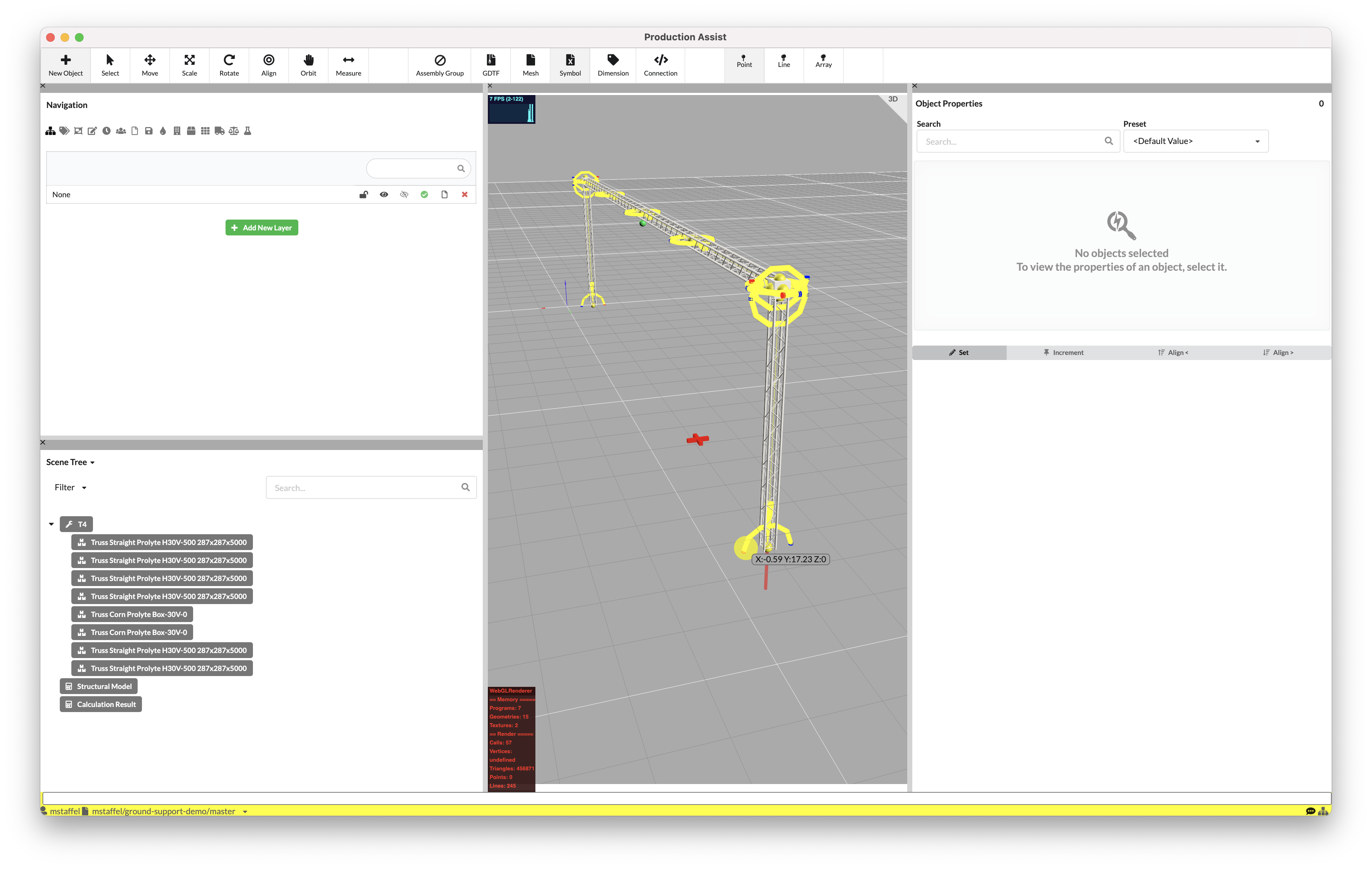
The red window at the bottom of Production Assist informs you about the current calculation status. Since this truss line currently has no load introduction or support, the calculation still fails.

NOTE: If you want to turn off the calculation while drawing, you can easily do so by deactivating the calculator symbol in the Information Line at the bottom right. If you only want to turn off the error messages for the system, you can click on the Tag symbol to the right of the calculator.

Loads are introduced into your system by attaching symbols to your structural objects. You can do this via the Toolbar and New Object or you position already inserted objects in your drawing on the structural element. Make sure they are at the height of the structural element. Then check that for all objects in the Object Properties under Inventory the correct weight is entered in the Weight field. This value is used for the calculation.

If you only want to insert a simple weight, you can also find a Generic Weight in the Resources under Generic → Weight, which you can insert and then assign the correct weight.
For Production Assist to know where your system is hung or connected to the ground, suspension points or ground anchors must be inserted. Via New Object in the Toolbar, various hoists, attachment points, or special Ground Support Attachments are available in the Resources.

Select these and position them on your structural elements. Make sure they snap and then check in the Object Properties that their values such as load capacity etc. are correct.
To perform static calculations, all objects that are to be calculated must be grouped into load groups. The safety factors are defined via these load groups. For example, the weight of all trusses can be multiplied by 1.1 to account for the weight of rigging hardware in the calculation.
You can add a new load group in the Navigation in the Load Groups tab via the Add New Load Group button and change the name and calculation factor by clicking on them and delete them via the red cross symbol.

To add objects to the load group, activate them in the Scene Tree or Renderer and look for the Inventory section in their Object Properties. There you can select the load group to which they should be added under Load Group.
To perform static calculations, all objects that are to be calculated must be grouped into load groups. The safety factors are defined via these load groups. These Load Groups can then be calculated in various combinations (Load Combination).

| Name | Description |
|---|---|
| Load Combination Settings | This is a button that opens a modal where the user can edit the settings for the load combination. |
| Wind Angle | Specifies the angle from which the wind hits the structure. |
| Default Wind Speed qb | Shows the default wind speed used for the load combination calculations. |
| Default Wind Pressure qb | Represents the default wind pressure calculated based on the wind speed and building height. |
| Usability | A validation setting that checks the functionality and usability of the structure under the defined load combinations. |
| Eurocode Ultimate Failure | A validation setting that checks compliance with Eurocode standards for maximum load capacity and safety. |
| Order Certified Statics | Allows requesting certified statics to ensure that the design meets safety and compliance requirements. |
| Price | Opens a modal where the user can request the certified statics calculation and complete the order with all details (e.g., items, quantity, coupon). |
| Add New Load Combination | A button that allows the user to create a new load combination. |
After the load combination has been created, the name can be changed by clicking on it and it can be activated via the green dot. If factors need to be changed, this can be done via the pencil symbol and the load combinations can be deleted via the red cross symbol.
You can add a new load combination in the Navigation in the Load Combination tab via the Add New Load Combination button. The Edit Load Combination Window opens. Here, general calculation values for dynamics or Eurocode calculations can be assigned to the load groups or they can be excluded from the calculation by entering a "0".
By clicking on the red 'Order Certified Statics...' button or the green button, the table for ordering and statics calculation is opened.

| Name | Description |
|---|---|
| Order | Shows an overview of the available items (e.g., Supports, High Workload Support, Truss) and their quantities that are part of the statics calculation. |
| Active Statics Calculations | A button that opens a list of already performed or ongoing statics calculations. |
| Redeem Coupon | Allows the user to enter a coupon code to apply discounts to the total cost. |
| Coupon | An input field where the user can enter a coupon code to apply discounts. |
| Email Address for Questions | A field where the user can provide an email address for inquiries. |
| Order Number/Reference Number | Optional field where a reference number for the order can be specified. |
| Phone Number for Questions | Allows the user to provide a phone number for inquiries. |
| Purchase Certified Statics Calculation | The green button to complete the order and request the certified statics calculation. |
| Cancel | The red button to cancel the process and close the modal. |
By clicking on 'Load Combination Settings', the modal is opened showing the table for editing the load combinations.

| Factor | Describes the factor by which all loads from this load group are multiplied. |
|---|---|
| Cable Allowance for Trusses and Other Cross-Sections | Considers the estimated weight of cables resting on trusses and other structural cross-sections. |
| Cable Allowance for Pipes | Records the estimated cable weight resting on pipe structures. |
| Second Order Calculation | Considers the effects of deformations on the behavior of the structure under load. This includes both the displacement of the entire structure and local deformations of individual components. This calculation method ensures a precise analysis of the stability and safety of structures. |
| Calculate Internal Members | Activates the calculation of internal forces and moments within the members of the structure to precisely analyze the load. |
| Use Ground as Support | Allows the ground to be considered as an additional support in the calculation of load distribution in the structure. |
| Allow Uplift Forces from Ground Support | Allows the consideration of uplift forces that may act on the structure through the ground supports. |
| Floor | Defines the floor or level in a multi-story system to which the calculation refers. This affects load distribution and structural analysis. |
| Calculate Compensated Chain Shortening | Calculates the effects of chain shortening caused by loads and adjusts the calculation accordingly. |
| Use Level Factors from Load Case Combination of Supports | Uses factors from load case combinations to more accurately consider the loads at the supports of the structure. |
| Check Interaction of Each Part of the Truss | Performs a check to ensure that all parts of the truss interact harmoniously and stably together. |
| Deformation Limit | Limits the maximum allowable deformation of the structure to ensure stability and safety requirements. |
| Deformation Limit 1/L | Sets the allowable deformation limit as a ratio (e.g., 1/200), where the deformation is limited relative to the length of the component. |
| Apply a Vertical Load Based on the Total Load | Considers a vertical load based on the sum of the total load of the structure to enable a more accurate analysis. |

| Factor | Describes the factor by which all loads from this load group are multiplied. |
|---|---|
| Deformation Limit for Level | Defines a specific deformation limit for each level to ensure the stability of the structure. |
| Layer Name | Shows the names of the levels. |
| Deformation Limit for Level 1/L | Sets the deformation limit for each level as a ratio (e.g., 1/200), where the deformation is limited relative to the length. |
| Disable Cable Load for Level | Allows disabling the cable load for specific levels to adapt the calculation to specific requirements. |

| Factor | Describes the factor by which all loads from this load group are multiplied. |
|---|---|
| Wind Load Settings | This section contains the parameters for calculating wind loads for the structure based on geographic and structural factors. |
| Country | Specifies the country for which the wind load calculation is performed. This affects the specific wind load zones and standards. |
| Wind Load Zone | Determines the wind load zone in which the structure is located, based on the geographic region and corresponding standards. |
| Building Height | Defines the height of the structure above ground in meters, which has a direct influence on the wind load calculation. |
| Wind Angle | Specifies the angle from which the wind hits the structure. This value is given in degrees. |
| Default Wind Pressure qb | Represents the default wind pressure, calculated in kilonewtons per square meter (kN/m²), based on regional conditions and standards. |
| Default Wind Speed qb | Specifies the default wind speed in meters per second (m/s), based on local wind load zones and building height. |
| Scripts for Verification | Allows running predefined scripts for the analysis and validation of the structure. |
By default, the two load combinations Eurocode9 for trusses and Usability for hoists are created. You can assign different load combinations to trusses and hoists. If you activate the orange dot for a load combination, it will be used for hoists/supports. If you activate the green dot for a load combination, it will be used for trusses/structures.
| Calculation According to | Load Case for Supports (blue) | Load Case for Cross-Sections (green) |
|---|---|---|
| Value Display Table: Force in Roof | ✅ | |
| Value Display Table: Force at Lifting Device | ✅ | |
| Value Display Table: Reaction Force | ✅ | |
| Value Display Table: Force Connected Structure | ✅ | |
| Value Display Table: Horizontal Force | ✅ | |
| Value Display Table: Global Force | ✅ | |
| Value Display 3D at HPs | ✅ | |
| Value Display 3D at Section Reaction | ✅ | |
| Value Display 3D Utilization | ✅ | |
| Value Display 3D Utilization Deformation | ✅ | |
| Value Display 3D Deformation | ✅ | |
| Calculation Report - Load Overview | ✅ | ✅ |
| Calculation Report - Hoist Results | ✅ | |
| Calculation Report - Drop Results | ✅ | |
| Calculation Report - Ground Support Results | ✅ | |
| Calculation Report - Cross-Sections | ✅ |
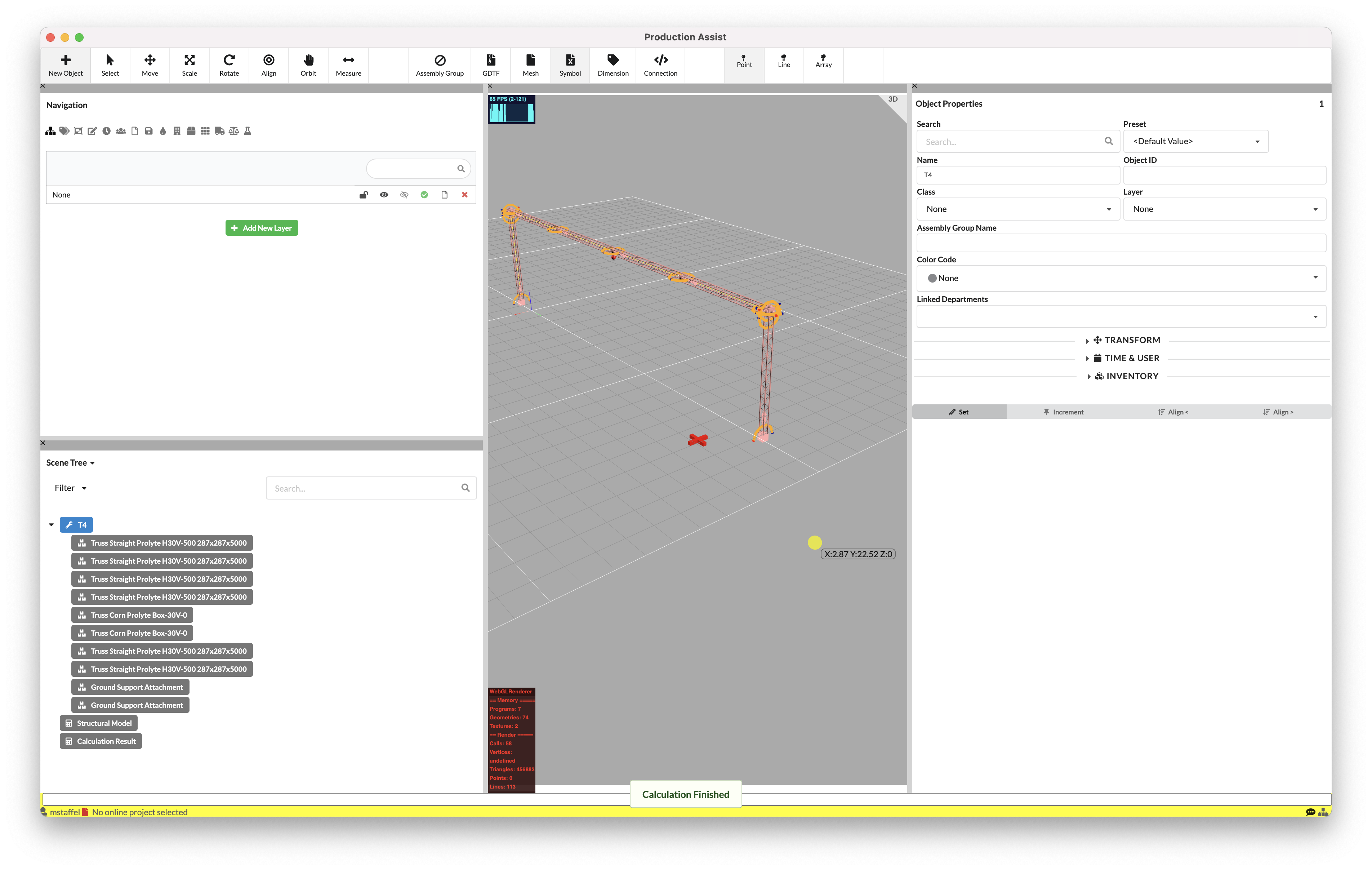
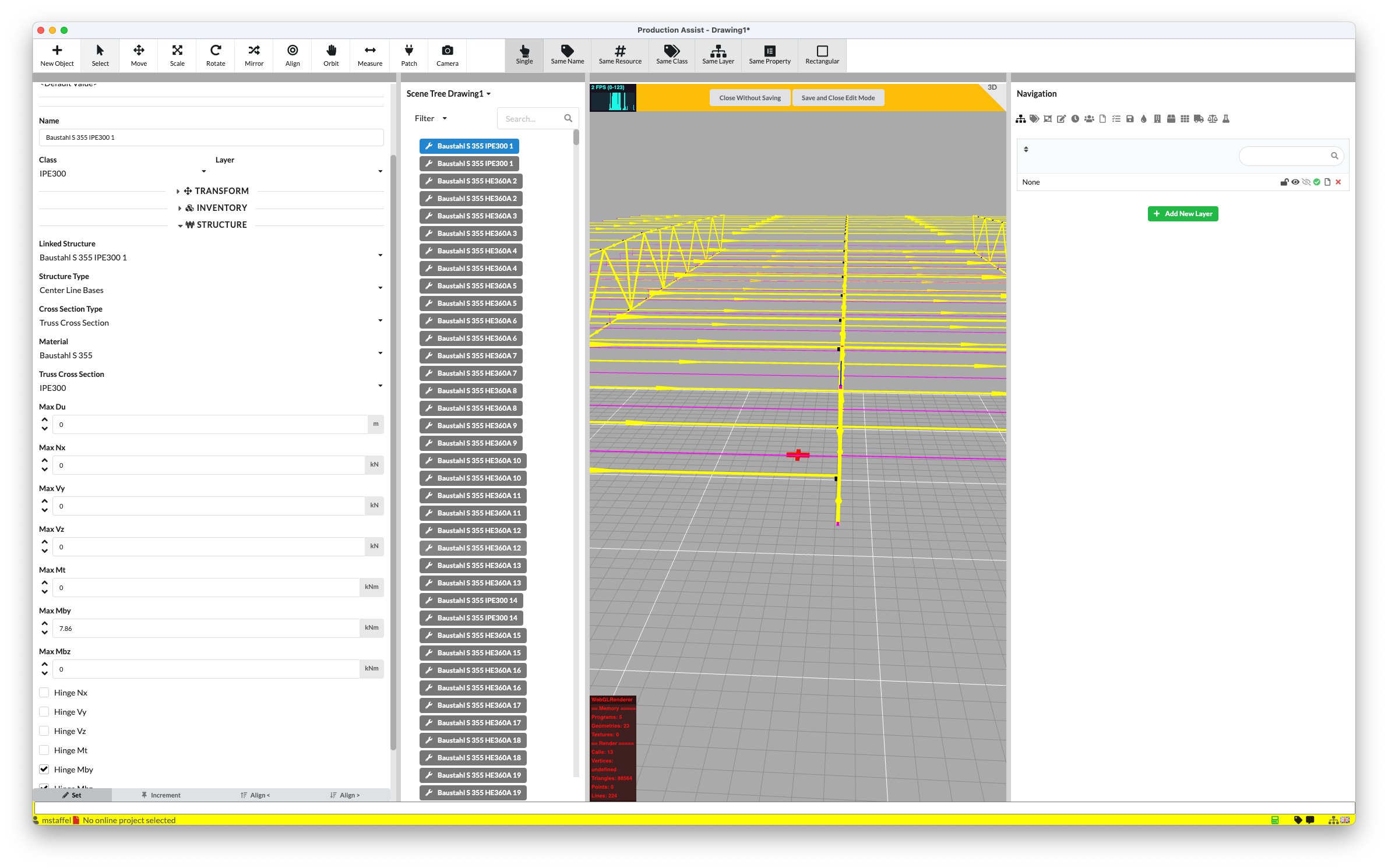
If the calculation is turned on, loads, structures, and suspensions/supports are positioned, the calculation is automatically executed. If successful, calculation results are also automatically inserted.
Activate the hoist or support symbols. In their Object Properties under Support you can view the results and also display them in the Renderer by checking Show Results in 3D.
The colors of the result structure in the Renderer also show you how your structural elements or your hoists/supports are loaded. Which values are decisive for this can be set in the Settings in the Menubar.
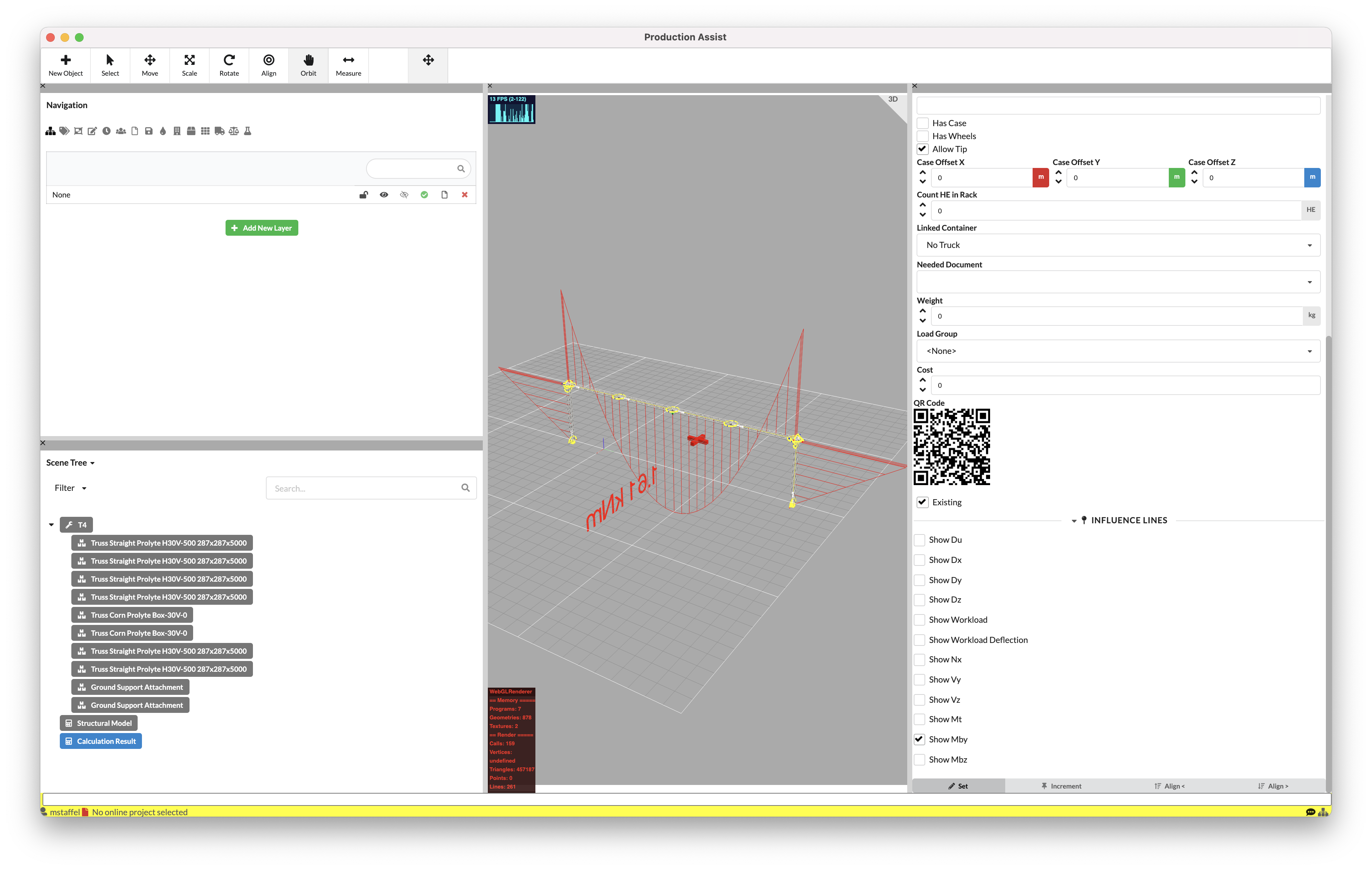
In the Scene Tree, two new objects appear automatically after a successful calculation: Calculation Results and Structural Model. To view the section reactions of the structural elements, select the Calculation Results object and in their Object Properties under Influence Lines, select the section reaction whose curve should be displayed in the Renderer.
A tutorial on static calculations can be found here.
If you want to turn off the automatic calculation, simply activate the calculator in the Information Line at the bottom right. If you activate it again, the calculation will be started.
If you only want to calculate specific objects in your drawing, you can add them to a temporary calculation group. To do this, activate them and select the Set Objects to Calculate command in the Menubar under Edit. They will turn red in the Scene Tree. Both individual objects and entire Assembly Groups can be activated. From now on, only these objects will be calculated. If you want to calculate all objects again, select the red-colored objects again and choose the Remove Objects to Calculate command in the Menubar under Edit. They lose their red color and all objects will be calculated again.
In the Menubar under File you can set the following points for the calculation in the Settings:
| Name | Setting |
|---|---|
| Show Structural Errors | Here you can set whether hints about the static system - for example, load is not attached or system not connected - should be displayed during drawing. You can also turn these on or off in the Information Line using the Tag symbol. |
| Workload Coloring Mode | Here you determine what the color of the result structure after calculation in the Renderer should be based on. Threshold means that it changes color from green to yellow or red when a certain value (Threshold) is exceeded, for example when an overload occurs. With the Gradient variant, the result structures are colored according to their utilization in the system from the lowest (green) to the highest (red) regardless of the magnitude of their values. |
| Description | Image | Solution |
|---|---|---|
| Two supports are in the same position. This happens when two supports overlap. | 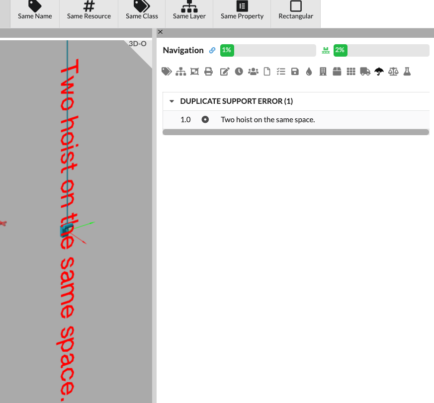 | Delete or move one of the supports. |
| Description | Image | Solution |
|---|---|---|
| A support fails in the calculation. This can happen when load-bearing elements unexpectedly deflect upwards. The example image shows this. | 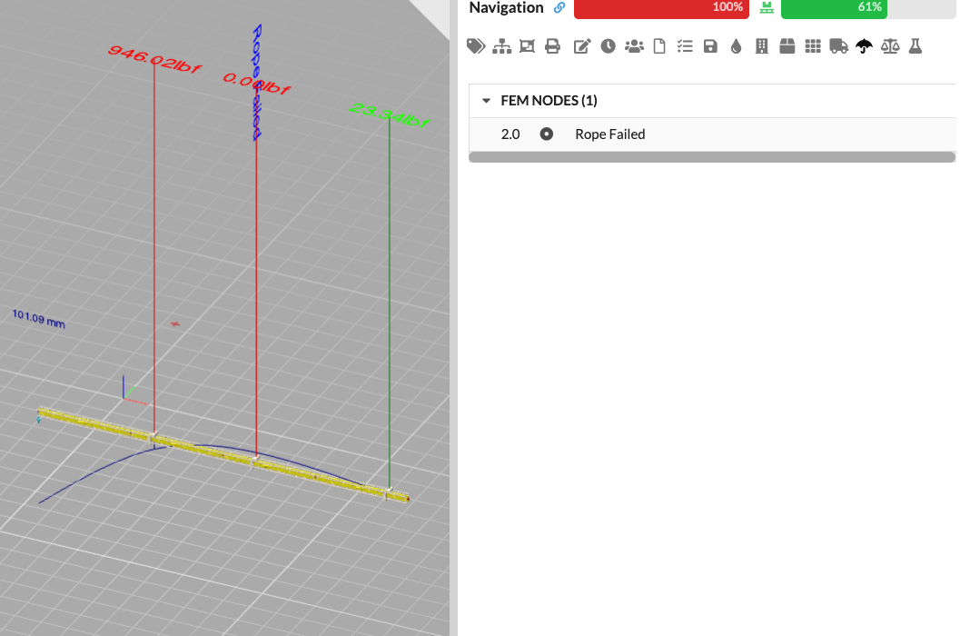 | Move the support so that the deflection changes. Alternatively, redesign the system. |
| Description | Image | Solution |
|---|---|---|
| There are no supports attached to a load-bearing element. | 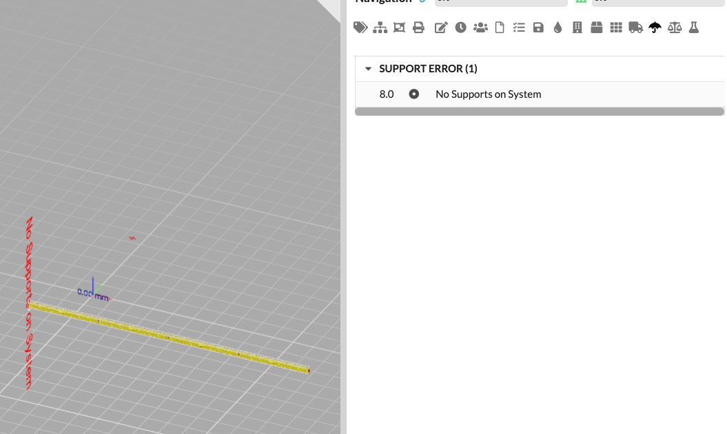 | Insert chain hoists or ground support attachments so that there are enough supports. |
| Description | Image | Solution |
|---|---|---|
| There are not enough supports attached to a load-bearing element. On a line there must be at least two supports, on a frame at least 3. | 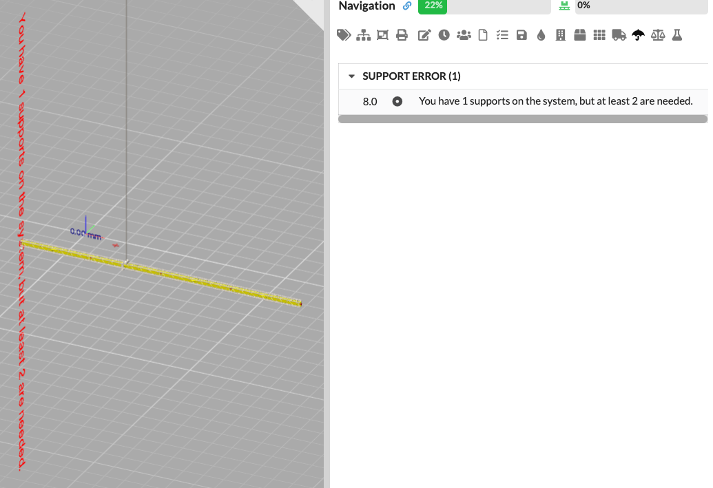 | Insert chain hoists or ground support attachments so that there are enough supports. |
| Description | Image | Solution |
|---|---|---|
| Two load-bearing elements from two different objects cross each other. At this point, the two load-bearing elements are assumed to be connected. | 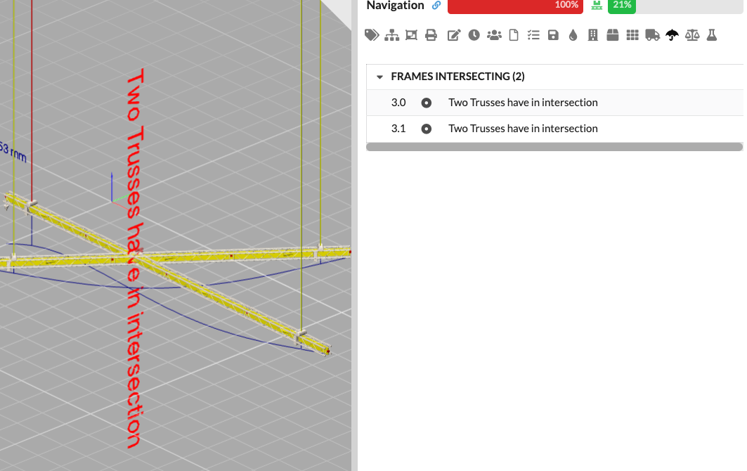 | Move the truss so that there is no longer any overlap. |
| Description | Image | Solution |
|---|---|---|
| A load has no weight. | 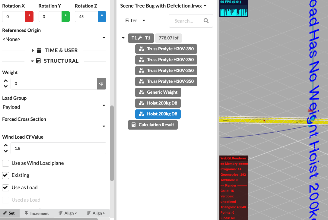 | Enter a weight for the load |
| Description | Image | Solution |
|---|---|---|
| A load cannot be assigned to a load-bearing element. For a load to be assigned to a load-bearing element, it must be within the truss box, with a tolerance of approximately 5cm. | 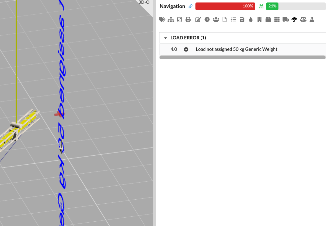 | Move the weight or exclude it from the calculation. |
| Description | Image | Solution |
|---|---|---|
| If a support cannot be assigned to a load-bearing element or load, an error is displayed. | 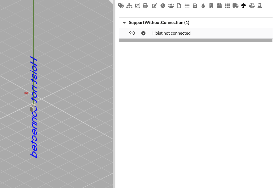 | Move the support or attach a load to it. |
You can also add calculation results as an additional load limit to a structural system, for example to define the maximum load of a support structure. This way you can also import the DSTV of a hall structure and then define the maximum loads for future calculations with this command.
To do this, select the Store Structural Results as Maximum command in the Menubar under Edit. After the calculation, you can set which results should be saved as reference values.
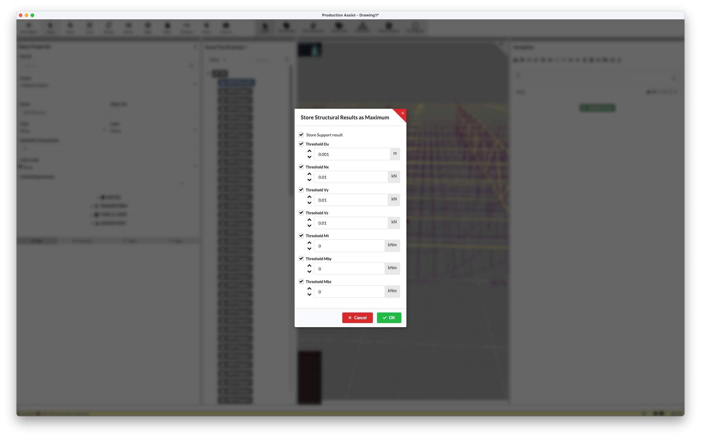
The results are written to the symbol definition of the structural elements. You can view them at any time in the symbol using the Edit Mode.
More on the topic of symbol structure and Edit Mode can be found here.
After your calculation, you can export a report with all results and verifications as a PDF.
To do this, click on the Create Calculation Report command in the Menubar under File.
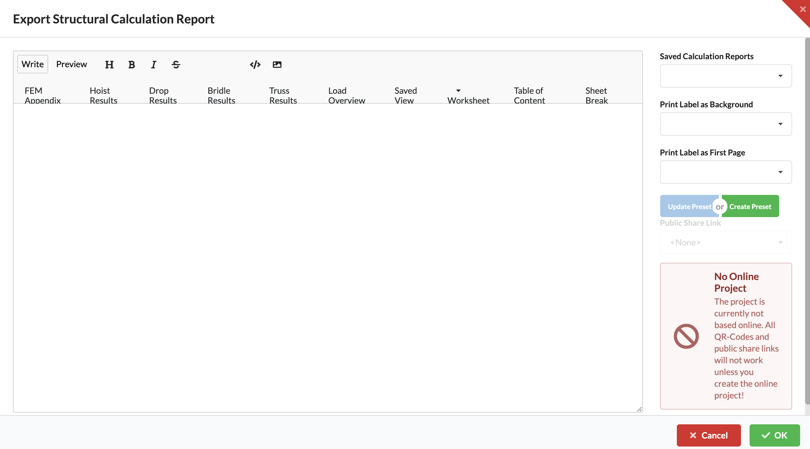
A window opens where you can switch between the creation view (Write) and the preview (Preview) at the top left.
The buttons below are used to insert the various verifications in your desired order.
| Report Section | Description |
|---|---|
| Sheet Break | Inserts a page break in the document. |
| Table of Content | Inserts a table of contents. |
| Worksheet | Inserts a worksheet. By clicking on the arrow, you can select whether the worksheet should display all elements of the drawing (Scene) or those of an Assembly Sheet. |
| Saved View | Inserts a saved view (Saved View). |
| Load Overview | Inserts an overview of all loads. |
| Truss Results | Inserts the calculation results for the cross-sections of the structural elements. |
| Bridle Results | Inserts the calculation results for the bridle utilization. |
| Drop Results | Inserts the calculation results for the load on the truss connections. |
| Hoist Results | Inserts the calculation results for the chain hoist utilizations. |
| FEM Appendix | Inserts the appendix with information on all calculation nodes so that the calculation could be reviewed by another person. |
In addition to these elements, you can also write text between the sections and format it using the symbols next to Preview. This text will then appear as plain text in the report.
On the right side of the window there is also the option to insert backgrounds for the PDF and/or the title page. In addition, the inserted elements can be saved as a template in their order and with the background.
When you have set everything as desired, press the green OK button in the lower right corner. You will be asked for the name and storage location for your calculation report and then your PDF will be exported.
| Command | Description |
|---|---|
| %%SHEETBREAK%% | Inserts a page break in the PDF. |
| %%LINEBREAK%% | Inserts a line break in the PDF. |
| %%QR_CODE_PROJECT%% | Inserts a QR code that links to the entire project. |
| %%QR_CODE_WORKSHEET()%% | Inserts a QR code for a specific worksheet. |
| %%TEMPLATE_WORKSHEETS()%% | Inserts all worksheets of the current project. |
| %%QR_CODE_OBJECT()%% | Inserts a QR code that links directly to a specific object. |
| %%WORKSHEET()%% | Inserts a worksheet that shows an overview of the current scene or a group. |
| %%ACAD_LAYOUT()%% | Inserts an AutoCAD layout view into the PDF. |
| %%SAVED_VIEW()%% | Inserts a saved view from the 3D renderer into the PDF. |
| %%TOC()%% | Adds a table of contents for the PDF. |
| %%FEM_APPENDIX%% | Inserts an appendix with all FEM nodes for detailed review. |
| %%HOIST_RESULTS%% | Shows the results of the chain hoist calculation. |
| %%DROP_RESULTS%% | Shows the results for loads at connection points. |
| %%BRIDLE_RESULTS%% | Shows the results for bridle loads. |
| %%BRIDLE_RESULTS_NO_LEGS%% | Shows the bridle results without leg supports. |
| %%GROUND_SUPPORT_RESULTS%% | Shows the results for ground supports. |
| %%TRUSS_RESULTS%% | Shows the results of the cross-section calculation for trusses. |
| %%TRUSS_RESULTS_WITH_ROPES%% | Shows the truss results including attached ropes. |
| %%LOAD_OVERVIEW%% | Inserts an overview of all loads in the system. |
| %%LOAD_COMBINATION%% | Shows the currently used load combinations. |
| %%HOIST_RESULTS_SCOPED()%% | Shows filtered results for specific chain hoists. |
| %%DROP_RESULTS_SCOPED()%% | Shows filtered results for specific drops. |
| %%BRIDLE_RESULTS_SCOPED()%% | Shows filtered results for selected bridles. |
| %%BRIDLE_RESULTS_SCOPED_NO_LEGS()%% | Shows filtered bridle results without leg supports. |
| %%LOAD_OVERVIEW_SCOPED()%% | Shows a filtered overview of selected loads. |
| %%BRIDLE_RESULTS_SCOPED_NO_LEGS()%% | Shows filtered bridle results without leg supports. |
| %%TRUSS_RESULTS_SCOPED()%% | Shows filtered truss results for specific cross-sections. |
| %%TRUSS_RESULTS_WITH_ROPES_SCOPED()%% | Shows filtered truss results including attached ropes for specific areas. |
| %%HOIST_RESULTS_FILTERED()%% | Shows filtered results for chain hoists according to specific criteria. |
| %%DROP_RESULTS_FILTERED()%% | Shows filtered results for drops according to specific criteria. |
| %%BRIDLE_RESULTS_FILTERED()%% | Shows filtered results for bridles according to specific criteria. |
| %%LOAD_OVERVIEW_FILTERED()%% | Shows a filtered load overview based on specific criteria. |
| %%GROUND_SUPPORT_RESULTS_FILTERED()%% | Shows filtered results for ground supports. |
| %%TRUSS_RESULTS_FILTERED()%% | Shows filtered truss results. |
| %%TRUSS_RESULTS_WITH_ROPES_FILTERED()%% | Shows filtered truss results including ropes for specific areas. |
| Command | Description |
|---|---|
| %%STAND_NAME%% | Inserts the name of the location or stage. |
| %%PROJECT_NAME%% | Inserts the project name. |
| %%VENUE_NAME%% | Inserts the name of the venue. |
| %%IMPRESSUM%% | Inserts the imprint or additional project information. |
| %%COMPANY_NAME%% | Inserts the name of the company associated with the project. |
| %%USER_NAME%% | Username of the currently logged-in user |
| %%REPORTER_NAME%% | Name of the user responsible for the static calculation. |
| %%PROGRAM_VERSION%% | Inserts the current version of the software. |
| %%CURRENT_DATE%% | Inserts the current date when the PDF is generated. |
| %%PROGRAM_BUILD%% | Inserts the build number of the current software version. |
| %%PROJECT_DATE%% | Inserts the date of the project. |
| %%CONSTRUCTION_DATE%% | Inserts the construction or setup date. |
| %%DISMANTLE_DATE%% | Inserts the dismantling or takedown date. |
| Command | Description |
|---|---|
| %% JSON_ENTRY %% | Inserts custom data from a JSON file. |