

Your first result: Insert a symbol into an empty drawing and save it on your computer. You do not need your own floor plan or an online project for this.
Install the desktop app and sign in with your Production Assist account. You need an internet connection for symbols from the online library. If you already have a local resource, you can use that too.
.lrwx file. To open it later, choose File → Open....In a new, empty file, Current Drawing initially contains no symbols in the resource selector. Switch to Online Drawing or Local Resources. If there are no results, check that Symbol is the selected type, clear any search term, and check your connection for online resources. The OK button only closes the selector; to activate a symbol, click Import... or Download & Import beside its entry.
If you already have a plan, read Importing existing plans. For fixtures with a GDTF file, see the GDTF steps below. You do not need to calculate the first object you save.
On first launch, you can start the introduction tour with Start Tour or close it with Cancel. Show on next program start determines whether the introduction appears again the next time you start the app. The links in the welcome dialog open the video tutorials or the user guide.
To view the tour later, choose Help → Getting Started....
At the top, the Menubar contains File and the other main menus. Below it is the Toolbar with the tools. The large drawing area is the Renderer. The Scene Tree lists the objects, Object Properties shows their settings, and Navigation is where you manage layers and classes, among other things. User Interface explains and illustrates each area individually.
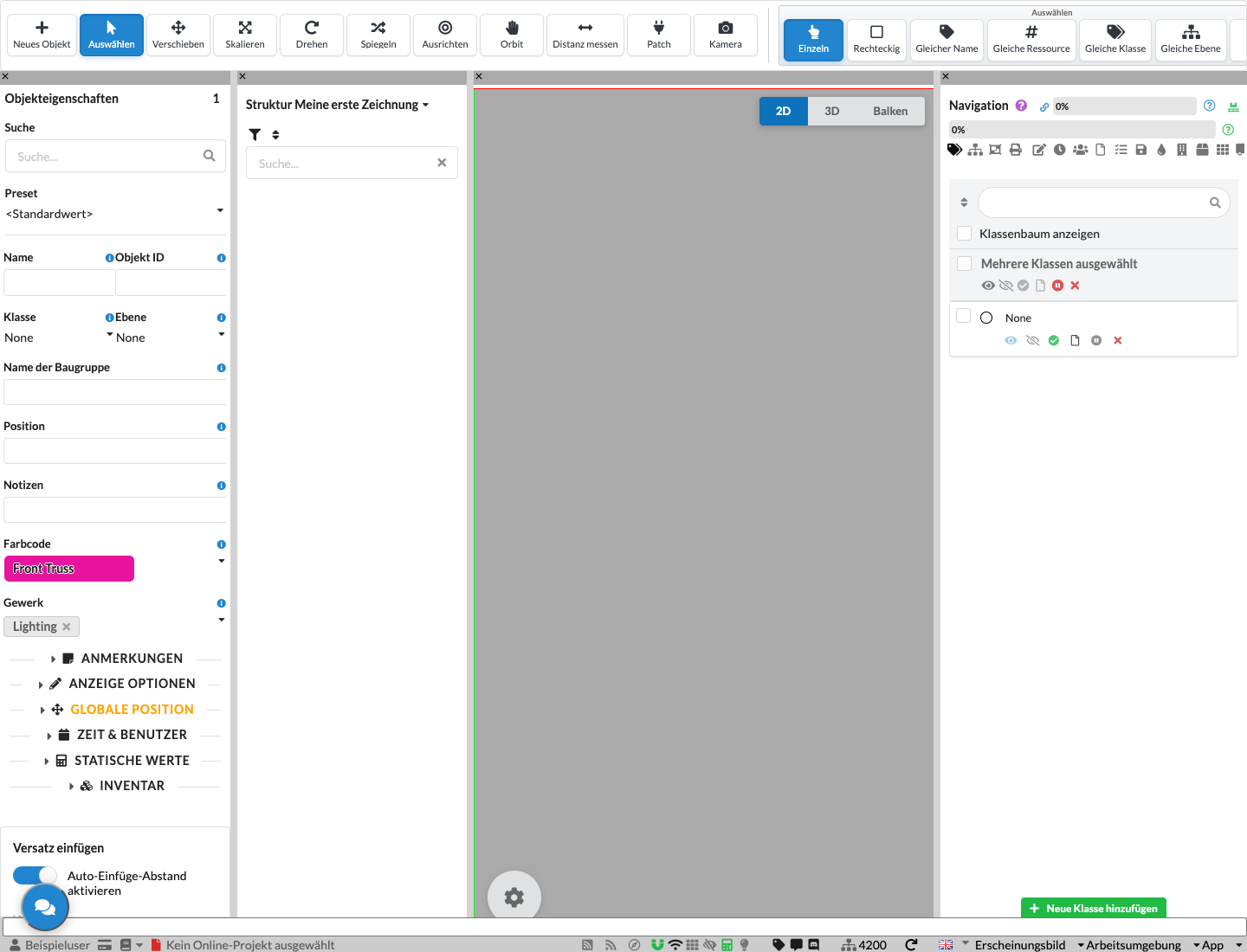
The image shows a new, empty drawing in 2D mode. The Scene Tree and Object Properties do not yet contain a selected object.
After starting Production Assist, a new empty drawing is already available. Import existing plans and 3D geometry using File → Import. Use Import DWG/DXF... to import a 2D floor plan from a DWG or DXF file. Import PDF... also imports a 2D floor plan if it is in PDF format. Import MVR... imports the 2D and 3D parts of an MVR document. Import Mesh... inserts 3D geometry.
If you are working with a CAD integration, follow the appropriate introduction for SketchUp, Vectorworks, or AutoCAD and BricsCAD. This quick start describes the standalone desktop app.
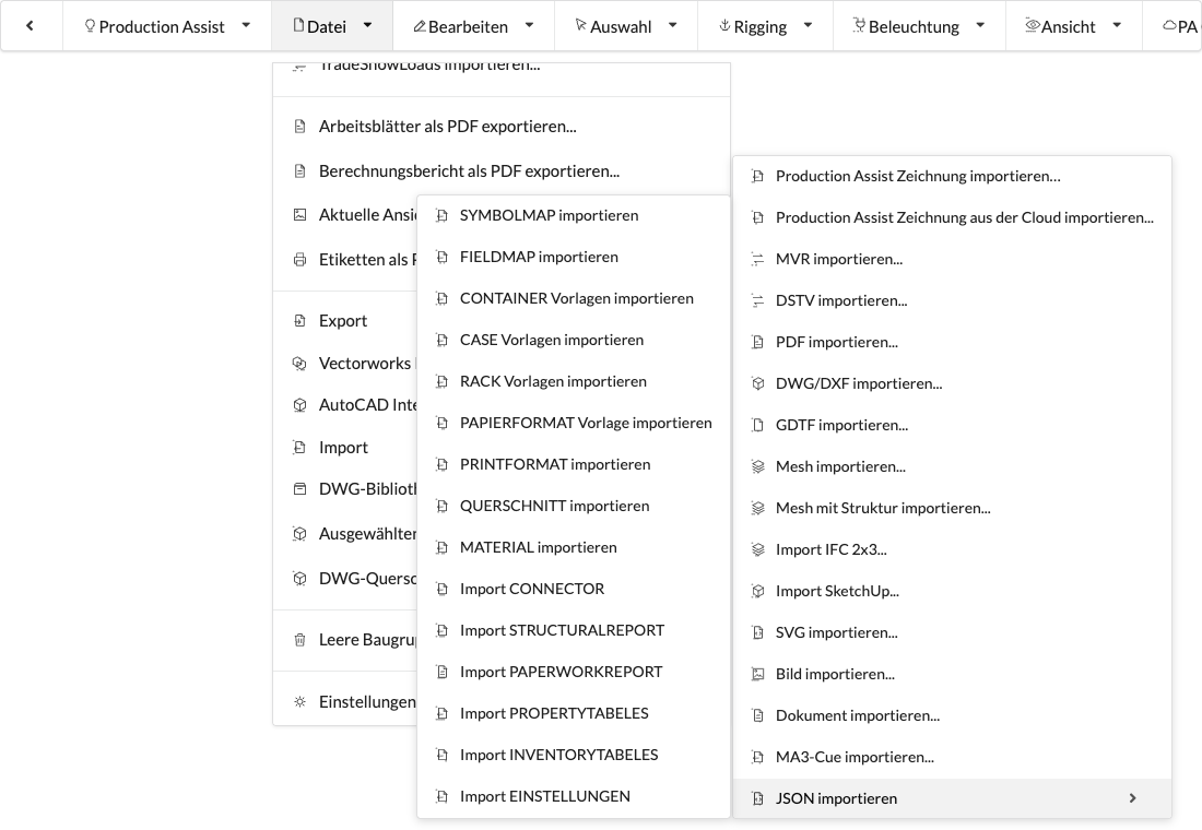
For more information on creating a plan with MVR, see the MVR import quick start.
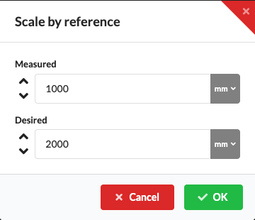
An imported PDF floor plan may initially have a different scale from the real plan. Scale it using a known distance:
Example: If the distance measured in the PDF is 1 m but is actually 5 m, enter 5 m under Selected.

Choose New Object in the Toolbar to switch to insertion mode. Use the type selector in the toolbar to choose which kind of resource to insert:
| Type | What you can insert |
|---|---|
| Symbol | Production Assist symbols from the library, such as trusses, power distributors, chain hoists, or video objects. A symbol can contain additional information and properties as well as its 3D geometry. |
| GDTF | Devices from GDTF files. GDTF is a format for describing lights and other devices. For example, you can download a GDTF file from GDTF Share and then load it into Production Assist. |
| Mesh | Simple 3D bodies inserted into the drawing as geometry or decoration. A mesh contains the body's 3D surface. |
The resource selector opens automatically the first time you activate New Object if the drawing does not yet contain any available symbols. If New Object is already active, click it again to reopen the selector. You can also open it by clicking Symbol, GDTF, or Mesh in the Toolbar. In the selector, choose the resource type at the top and the source below it.
Current Drawing contains resources available in the active drawing. Local Resources contains locally stored content, Online Drawing contains Production Assist resources available online, and User Resources contains resources from the selected user account. You need an internet connection for online content.
If the current drawing does not yet contain a suitable fixture type, choose Online Drawing or Local Resources. Clicking OK alone does not import a resource.
Choose the resource you want and click Import... beside its entry. Download & Import is available for an online resource that is not yet available locally. You can then place the object by clicking in the Renderer. Further clicks insert more objects of the same resource. Press X (the default shortcut for single selection) to return to the selection tool.
Production Assist trusses already contain the connection magnets in their symbols. Move the truss you are inserting to a magnet point on an existing truss. If the objects can connect there, Production Assist shows a red connection preview. Click to insert the truss aligned precisely at that point.
Press Shift to rotate the orientation of the truss being inserted in 90° increments. Press Ctrl (Windows) or Control (macOS) to switch between the magnets on the truss being inserted and thus between its insertion points. This is especially useful at corners when you need to select the appropriate connection point. Use the Control key for this, not the Meta or Command key.
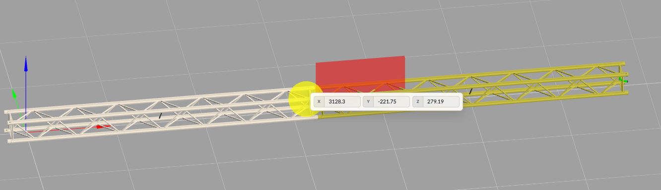
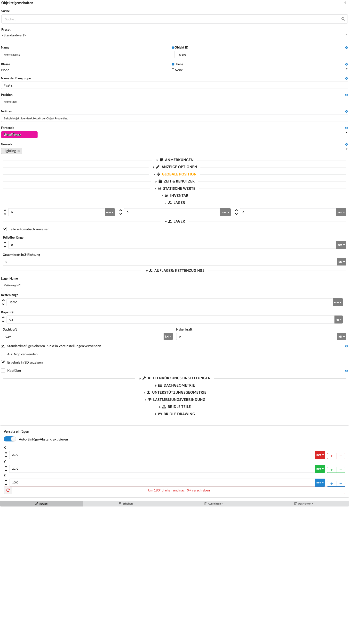
Select the inserted object to adjust its Object Properties in the corresponding palette, such as its name, position, electrical connections, and object details. The Scene Tree shows the selected object in the object list.
Use the mouse wheel to zoom in and out on objects. The Toolbar also contains tools to rotate, scale, mirror, and move objects.
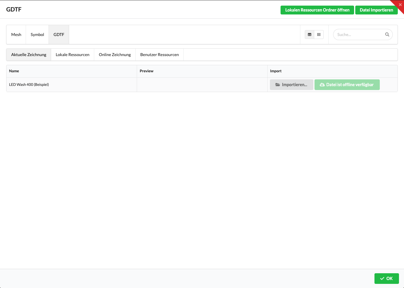
GDTF (General Device Type Format) is a comprehensive format containing all the information needed to describe a light or another device.
First import a GDTF file as a fixture type into the current drawing. This alone does not place a spotlight in the plan:
.gdtf file on your computer. Production Assist displays a confirmation if the import succeeds.Alternatively, in the open GDTF resource dialog, use Import File to select a .gdtf file and then insert the imported fixture type.
Imported fixture types from GDTF that are used in the drawing can be found in the Resource Manager under Fixture Types. Insert them into the drawing using New Object → GDTF.
Insert chain hoists in the same way as other Production Assist symbols:
To obtain calculated forces, you also need a complete model that can be calculated. The structural calculation guide explains the required steps. After a successful calculation, you can display the support forces on a chain hoist in the Renderer:
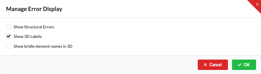
To display structural diagrams on the structural members, after the calculation open the Section Reactions tab in Navigation. Depending on the analysis you want, activate Show Utilization, Show Relative Deflection, Show Bending Moment Mby, or Show Bending Moment Mbz. The available options depend on the calculation results. Show Result in 3D also displays numerical values on the result diagrams, if the result type and CAD host support those labels.
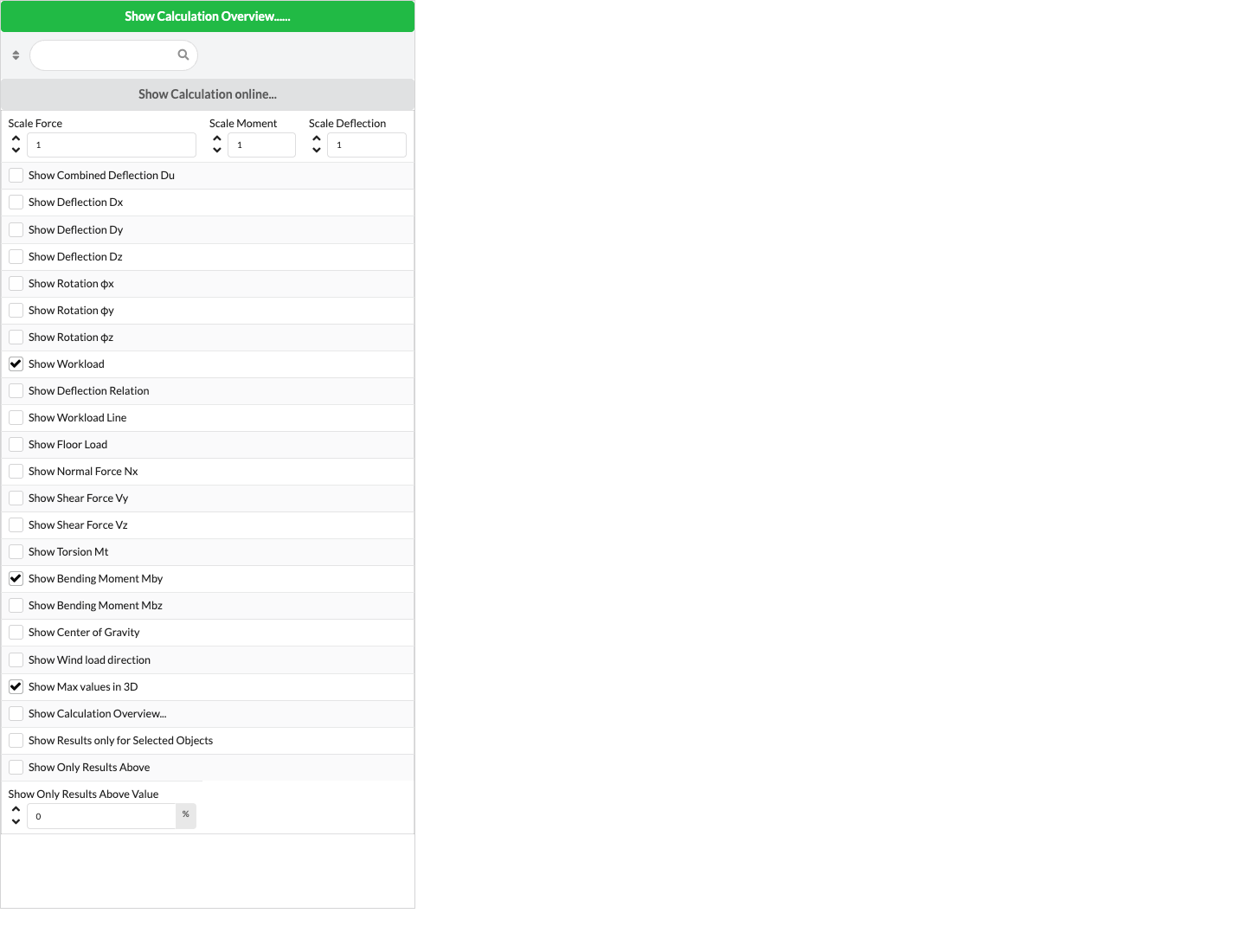
For more information about prerequisites and result displays, see Calculation results and Navigation: Section Reactions.
The Scene Tree is the hierarchical object list for your drawing. Indented objects belong to a parent group (Assembly Group). This makes it easier to see which objects are related and to find, select, and edit them together in the tree. Expand or collapse groups to keep the view organized.
The hierarchy helps you organize your drawing, but it does not control which objects are visible in the Renderer. Use layers and classes in Navigation to show or hide objects. The Scene Tree filter can further narrow the object list. See the Scene Tree chapter for more ways to use it.
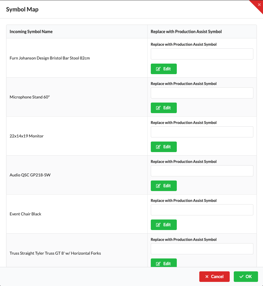
When importing an MVR, Import Groups is initially enabled in the Symbol Map dialog. If the MVR file contains groups, they are imported as Assembly Groups. If you disable this option, the contained objects are imported without those groups. Check the Scene Tree after import and group objects yourself if needed.
If you have already organized your drawing with layers or classes, you can group the objects in the Scene Tree afterward. In the Menubar, choose Edit → Group By, then Group by Class or Group by Layer. This organizes the objects in the tree by class or layer and makes it easier to navigate. It does not change their visibility in the Renderer. You do not need a group for your first saved drawing.
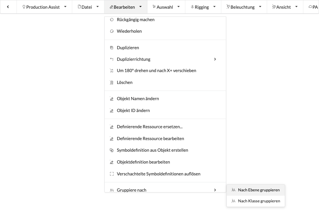
This gives you an overview organized by class or layer, for example for venue or set objects. To create your own group for trusses and fixtures:
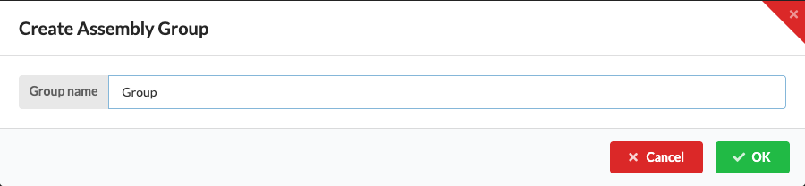
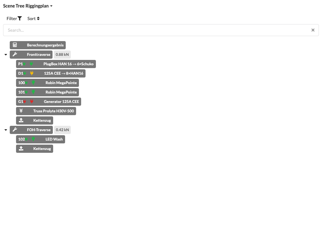
You can create more Assembly Groups and rearrange objects in the Scene Tree using drag and drop, or drag objects into a group. The Scene Tree filter helps you find specific objects. Control visibility using Layers and Classes in Navigation.
Use the lock to lock or unlock a layer. Its objects remain visible but cannot be edited; classes do not have a lock here. The black eye shows or hides the objects on a layer or class in the Renderer and Scene Tree. The gray eye isolates a layer or class and hides the others.