

Production Assist converts the wind action on an object into forces and transfers them to the connected structural system. For the calculation to meaningfully represent the real load-bearing behavior, the wind-exposed area, wind parameters, connections, and supports must be consistent.
This page explains how wind loads arise, how Production Assist transfers them to the structure, and how to check the applied load in the wind load images.
In simplified terms, wind-load calculation consists of five steps:
Wind direction is crucial. An area can have a large wind-exposed area when the wind strikes it head-on and be almost ineffective when the wind flows parallel to it.
In Object Properties, specify whether structural elements of an object should carry wind loads. The Capture Wind Load option controls this; you can exclude individual elements, such as scaffold diagonals. Then select exactly one method under Wind Load Type for Production Assist to determine the wind-exposed area. The drawings below are schematic examples, not views of the application.
| Option | Suitable for | Calculation basis |
|---|---|---|
| Use as Wind Load Plane | Banners, walls, and other closed surfaces exposed to wind from the side | A 2D polygon in the object defines the closed wind-load area; 3D bodies do not replace this polygon. No wind load is generated when the wind is parallel to the area. |
| Use as Roof Wind Plane | Closed roof areas, such as the covering of a stage roof | A 2D polygon in the object defines the roof area. Depending on the setting, the load acts perpendicular to the roof as suction away from it or pressure toward it; a vertical area is unsuitable for this mode. |
| Use Structure as Wind Load Plane | Trusses, frameworks, and other open load-bearing structures | Production Assist derives the wind-exposed area from the structural geometry, its dimensions, and its lattice. The gaps are not treated as a closed area. |
| Use Geometry as Wind Load Plane | Compact 3D objects such as fixtures or decorative elements | The 3D geometry is projected onto a plane according to the wind direction. |
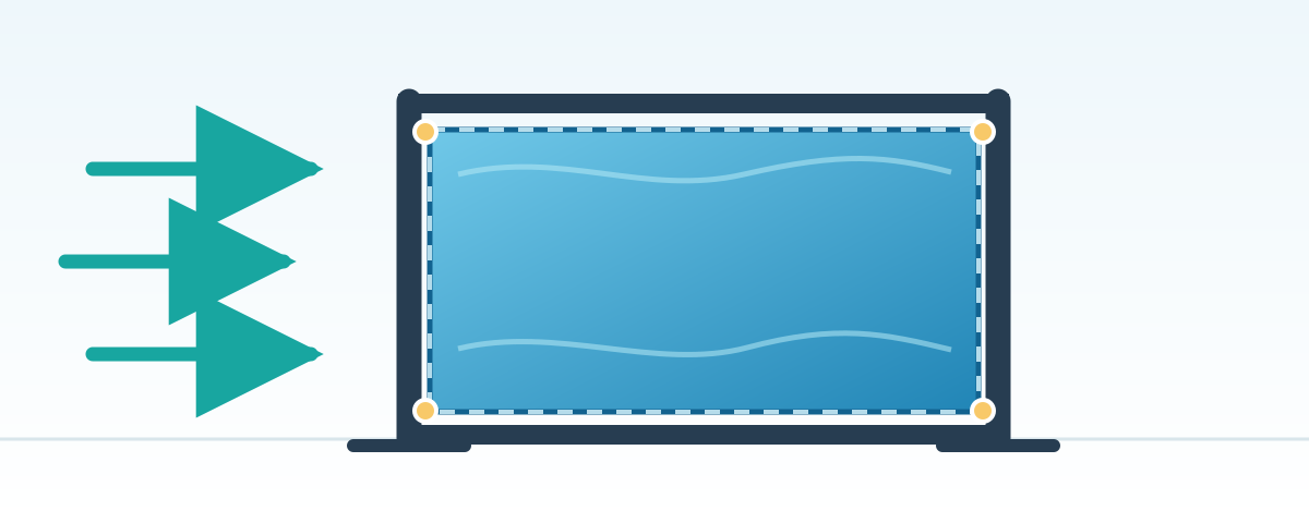
For a banner exposed to wind from the side, select Use as Wind Load Plane. The 2D polygon must describe the actual closed area, not just its supporting frame. The effective wind-exposed area changes with the wind direction; no wind pressure is applied when the wind runs along the area.
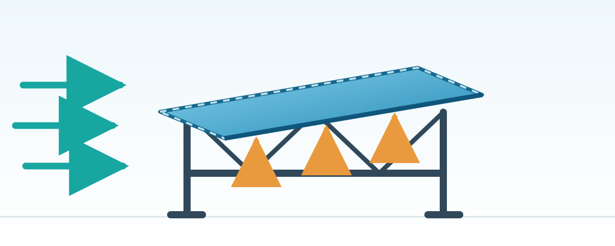
For a roof covering, select Use as Roof Wind Plane. The object needs a 2D polygon that describes the roof area. Production Assist uses its horizontal projection as the reference area, applies uniform wind pressure to it, and transfers the entire roof load over a grid to nearby structural elements that carry wind loads. The roof area can be sloped; a vertical area is not processed in this mode.
Only in this mode do Roof Wind Load Coverage and Roof Wind Load Pitch appear in Object Properties. Roof coverage describes how enclosed the space under the roof is: 0% means air can flow freely through it, and 100% means the underside is fully covered or blocked. It does not describe how much of the roof skin is covered by a tarp. The roof pitch is calculated from the geometry in the selected wind direction and displayed; you do not enter it manually. In the suction case, Production Assist determines the roof CF value from the roof pitch and roof coverage; in the pressure case, it uses the roof pitch. The regular Wind Load CF Value is not an input field when a roof wind plane is selected.
Under Navigation → Load Combinations → Wind Settings, Show Roof Wind Loads Downwards controls the load direction: when off, suction acts away from the roof; when on, pressure acts toward the roof. The force always acts perpendicular to the roof, so it also has a horizontal component when the roof is sloped. This setting is off by default and applies to the roof wind-load case of the load combination. Check both directions if they may govern the setup. The orange arrows in the diagram show the suction case as an example.
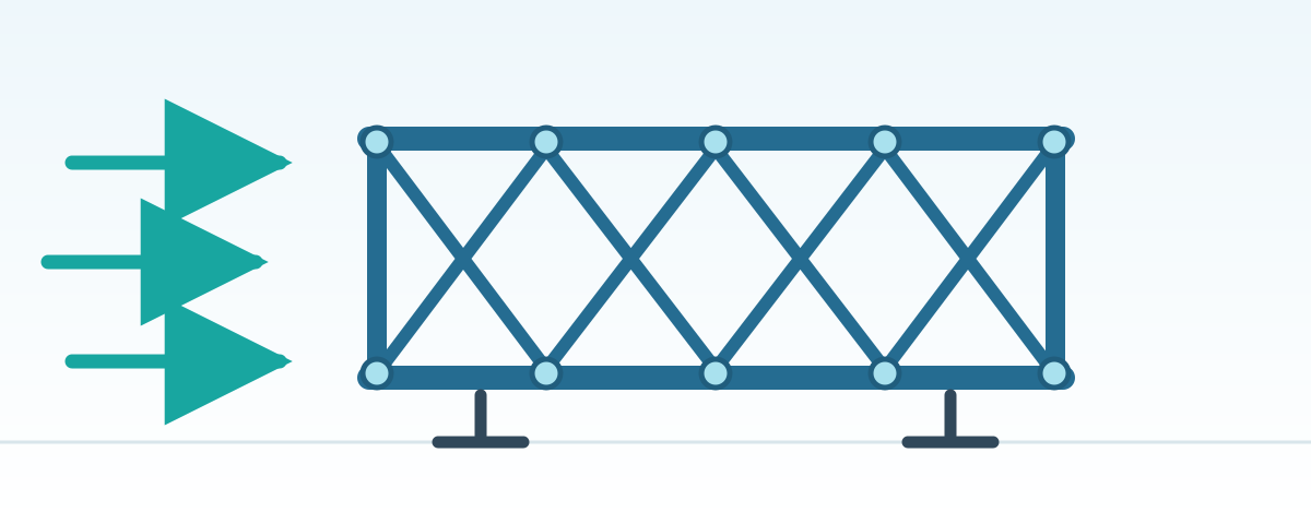
For an open truss, select Use Structure as Wind Load Plane. Production Assist determines the wind-exposed area from the structural elements present. A surrounding rectangular envelope would be too large unless there is a closed covering.
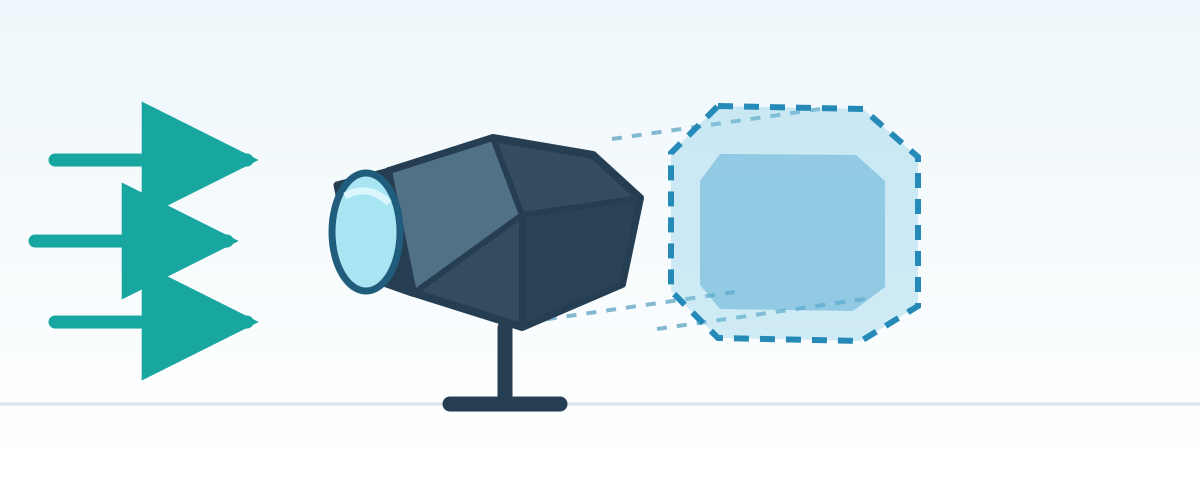
For a fixture or another compact 3D object, select Use Geometry as Wind Load Plane. Production Assist projects the body for each wind direction being examined. Check that the shape and orientation of the 3D model match the planned setup.
For a closed tarp, do not accidentally use only the open support structure as the wind-load plane. Conversely, do not treat an open truss as a completely closed wall without technical justification.
The Wind Load Area and Effective Wind Load Area values in Object Properties help you check the detected area. For the three modes other than the roof wind plane, the Wind Load CF Value must suit the geometry and applicable standard. If reliable data is unavailable, do not apply an arbitrary reduction to a wind-permeable tarp or LED wall without evidence.
Open Navigation → Load Combinations → Wind Settings and first select the Wind Load Type for the actual location and governing standard. The selection changes the wind-load model and may populate Standard Wind Pressure qb, height factors, and additional horizontal loads with default values. Check all populated values after each profile change.
| Wind-load type in the interface | When to use it | What to check |
|---|---|---|
| Eurocode Outdoor | Outdoor setup when the wind assumptions are defined under Eurocode and the applicable national annex. | Select Country, Wind Load Zone, and Terrain Category for the specific location; then check construction height, basic wind speed, and Standard Wind Pressure qb. There is no free-entry Location field here: the location is represented by country and wind zone. |
| Trade Show Indoor | Indoor setup in an exhibition hall when the project uses hall wind loads from this profile. | The profile sets a basic wind pressure of 0.125 kN/m² and its own height profile. These values are not an outdoor wind zone; clarify whether they match the hall operator's requirements or the applicable design basis. |
| Indoor ANSI E1.50-1-2025 | Indoor setup of a temporary display system, such as a large LED or video wall, when ANSI E1.50-1-2025 governs the project. | The profile sets 0.0958 kN/m² as a height-independent basic wind pressure. Check the object's Wind Load CF Value separately; selecting the profile does not set it automatically. |
| Indoor EN17879 2.5% | Indoor setup of an event structure when the design requires an additional horizontal load of 2.5% of the total vertical load under this approach. | The profile sets wind pressure to 0 and enables Horizontal Load from Total Load at 2.5%. It does not replace an explicitly required wind-area load. |
| EN13814 In Operation < 15m/s | Outdoor operation of an installation within the scope of EN 13814 when operation stops above the specified operating limit. | The profile sets a basic wind pressure of 1 kN/m² and height factors for the operating state. “15 m/s” is the operating profile name: do not also enter 15 m/s as a blanket value without checking the associated pressure assumptions. |
| EN13814 Out of Operation < 28m/s | Out-of-operation state of a corresponding installation, for example after removing banners or other wind-sensitive parts. | The profile also sets 1 kN/m² as the basic pressure and a stronger height profile for the out-of-operation state. “28 m/s” is the profile name, not an input field automatically set to 28 m/s. The model and selected objects must match the real out-of-operation state. |
EN 13814 applies to installations within its own scope, particularly amusement rides and related installations. The two EN 13814 profiles are therefore not a general choice for every temporary stage roof or other temporary structure. Likewise, ANSI E1.50-1-2025 is intended for temporary display systems. If the project requires another design basis, wind speed, or higher site wind load, the assumptions and model must match it. DIN EN 13814-1, DIN EN 17879, and ANSI E1.50-1-2025 describe the respective scopes.
For Eurocode Outdoor, the order matters: select Country and Wind Load Zone for the project location and Terrain Category for the actual surroundings. The zone provides a basic value; terrain and construction height affect the pressure at height. Compare the displayed values with the project requirements and national annex. DIN EN 1991-1-4/NA explains the national wind parameters for Germany.
The Standard Wind Speed qb and Standard Wind Pressure qb fields are linked: when you change the speed, the interface recalculates the associated basic pressure, and vice versa. This basic pressure is not yet the final wind force on the object. The selected profile may modify it based on height and other factors. A value such as 15 m/s in a profile name is therefore not a general value to copy into every project independently of the profile.
For the EN 13814 profiles, 1 kN/m² is set as the basic pressure and processed with the relevant height factors. The linked speed display for this basic pressure is mathematically about 40 m/s. This does not conflict with the profile names “< 15m/s” and “< 28m/s”: the names designate the intended operating states, while the display converts the unchanged basic pressure. Check the actual applied wind pressures in the Wind Summary and calculation report.
Also check Construction Height, Wind Direction or Calculate All Wind Directions Simultaneously, and, for roof areas, Show Roof Wind Loads Downwards. Temporary Use Factor changes the applied wind pressure. Use a reduction only when the standard and project data allow it for the specific service period and use; a temporary setup does not automatically justify a reduction.
A typical outdoor project has two states to verify: in operation, with the full equipment, and out of operation, after the measures actually planned, such as removing a banner. Enable Use Second Wind Pressure for this. Second Wind Pressure Settings then appear, with their own Wind Load Type, basic wind pressure or wind speed, and height factors. The second case does not automatically use the “Out of Operation” profile or set 28 m/s. Select and check each case separately.
Then assign each object to the appropriate setup state. Use at First Wind Speed and Use at Second Wind Speed determine whether the object is present in each calculation scope. A banner removed before the second wind case belongs in the first case, but not the second. The remaining structural system must still be included in the second case. Disable at First Wind Speed, by contrast, suppresses only the wind load generated by the object in the first case while keeping the object in the calculation scope. Check these three switches together so that the calculated setup matches the real operating state.
The EN 13814 profiles In Operation < 15m/s and Out of Operation < 28m/s can be a suitable pair for these two states when required by the standard and operating concept. The limits do not authorize continued operation above the limit or leaving unsecured components standing in the out-of-operation state. Other projects may require different limits and wind models.
The Wind Load CF Value is the object's aerodynamic force coefficient. In simplified terms, the force is wind pressure at the height being considered × effective wind-exposed area × CF value. The coefficient describes the overall force effect of the shape exposed to the wind, including pressure and suction. It is not a second area value or a free adjustment for eliminating an overload.
For banners, open structures, and compact 3D objects, enter the value in Object Properties → Structural Wind Load → Wind Load CF Value. The default value 1.8 is only a starting assumption. Determine the appropriate value for the actual shape, orientation, and wind direction from the governing standard, suitable manufacturer information, or documented test and inspection data. Make sure the coefficient refers to the same reference area used in the model. For trusses, Production Assist already accounts for the open structure in the area; do not reduce both the area and the CF value for the same gaps without justification. A reduction for nets and LED walls is appropriate only when supported by reliable data and a suitable design method.
For roof wind planes, Production Assist calculates the roof CF value from the roof pitch and selected pressure or suction direction; the Roof Wind Load Coverage is also used in the suction case. The regular Wind Load CF Value is not an input field in this case. Check the applied roof area, pitch, and underside coverage as carefully as a coefficient entered manually.
The Wind Load Images let you follow how Production Assist discretizes a wind-load area and transfers forces to the structural system. The command is available under Object Properties → Structural Wind Load and in the Wind Summary.
Alternatively, open Rigging → Show Calculation Summary... or, in the desktop app, the Calculation Results worksheet. In the Wind Summary, click the image icon next to the relevant entry. The Wind Summary also provides access to the images when you have not selected the object directly in Object Properties. The preview uses the wind directions and wind cases selected in the load-combination settings. In the dialog, the displayed wind angle is a label and cannot be changed there.
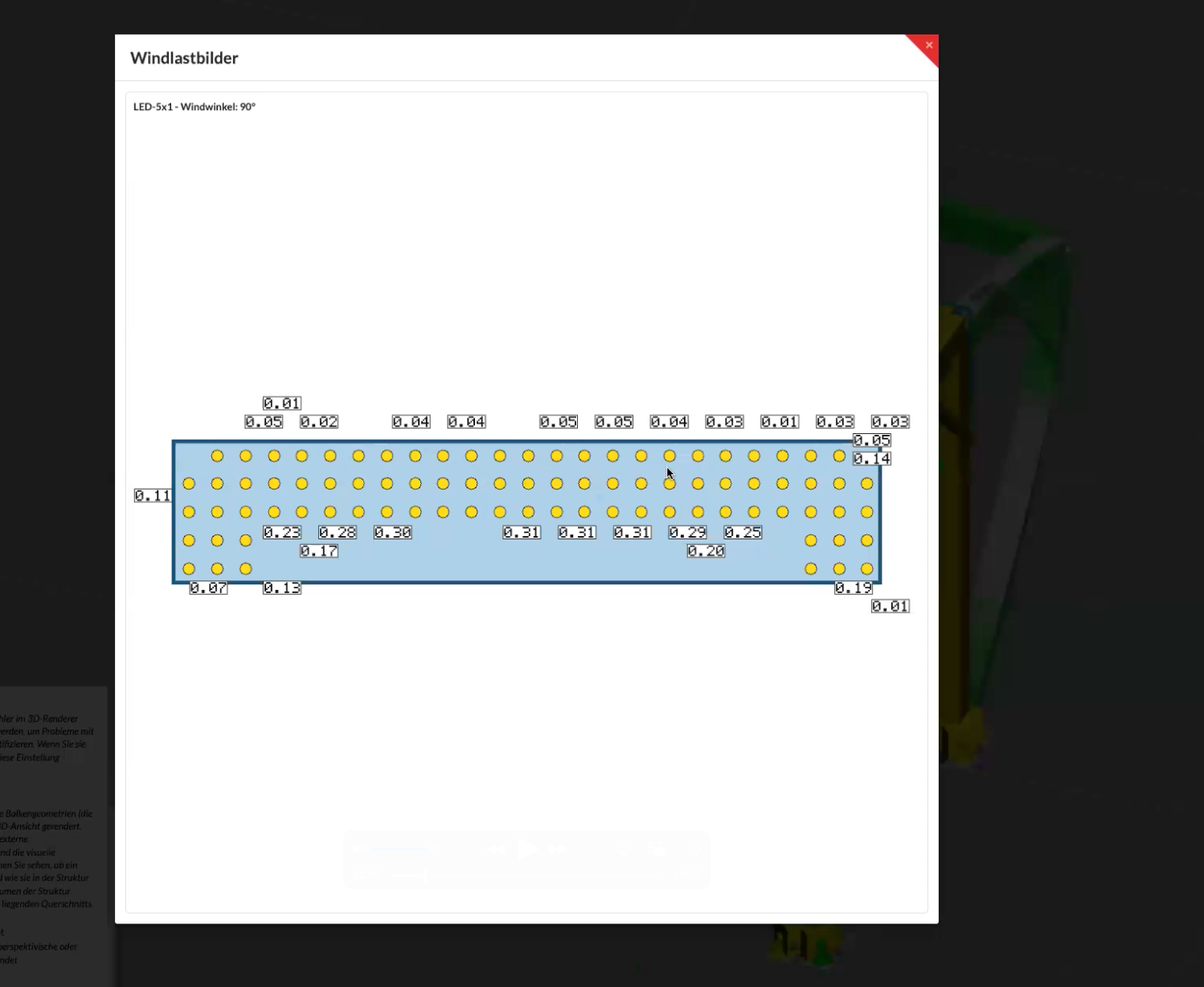
The Wind Load Images dialog is a read-only preview. Each available image appears as a tile with the object name, Wind Angle, and calculated graphic. Images from the second wind speed are labeled accordingly. The wind angle is a label; change it in the load-combination settings, not in this dialog.
While Production Assist generates the images, the dialog displays Generating Wind Load Images. If no preview is available, No Wind Load Images Available appears. If an error occurs, the dialog displays Could Not Generate Wind Load Images and the error text. Close the dialog with X, Escape, or by clicking outside the window. It has no other buttons.
The image shows an older preview with filled content. The current UI audit capture includes the dialog frame and a wind-angle label, but no wind-load graphic. It therefore does not replace this populated view.
In this view, the blue area marks the applied wind-load area. The yellow points show where the resulting forces are transferred to the structural system. Adjacent transfer points may share a force label. In that case, the numbers are sums for multiple points.
Large areas produce a correspondingly large number of transfer points. Their spacing also depends on the Mesh Resolution set under File → Settings... → Structural Settings. A finer resolution can represent small geometry changes more accurately, but increases calculation time. If no image is available, check that the selected object generates a wind load and has one of the wind planes enabled. While the preview is being calculated, the dialog shows a loading state; a calculation error produces an error message.
For roof wind planes, the applied wind pressure is uniform over the entire reference area. The forces at the individual transfer points depend on which portions of the area and neighboring components they carry. The same wind pressure therefore does not mean that each truss or point receives the same force. Similar, symmetrically arranged components receive approximately equal loads for a symmetrical roof area.
In the subsequent structural calculation, the stiffnesses, bracing, and supports of the actual structure affect the internal forces and support reactions. Differences in these results must match the modeled structural behavior.
If the load distribution is unexpected, check:
Do not assess a wind load from a single utilization color alone. Check all of the following together:
In the calculation report, Wind Load Combination shows the general formulas for wind speed and pressure before the parameter table for Eurocode terrain categories O to IV. Load Overview shows the assumed height and derivation of wind pressure or the resulting force for each captured object. If a second wind speed is enabled, its values appear in a separate overview. Compare height, wind pressure, and wind direction with the settings under Load Combinations; the formula values are displayed in the selected units.
The Wind Summary also displays a total row. It adds the areas for Wind Total Area and Wind Effective Area and the forces for Wind Total Force, Wind Total Force Usability, and Wind Total Force Eurocode. With a second wind speed, a separate Wind Summary with its own total is displayed.
Negative support reactions can indicate that the structure is trying to lift off or overturn at a support. In that case, model the supports, base plates, ballast, and bracing as they actually work in the real setup.