Creating Custom Structural Symbols in Vectorworks#
Custom Vectorworks symbols initially contain only their visible 2D or 3D geometry. For Production Assist to use a ballast block, ballast bed, base plate, or frame in a structural calculation, the symbol also needs a calculable structural model and, where applicable, support points.
There are two different workflows for this:
| Workflow | Suitable for | Basic concept |
|---|
| Edit an existing Production Assist symbol definition | Simple base plates, individual ballast bodies, and symbols with few functional points | Copy an existing intelligent symbol definition and adapt it in Edit Mode. |
| Evaluate Vectorworks classes with Structural Lines | Custom symbols with several members, connection heights, or support points | Lines and points inside the Vectorworks symbol are recognized as structure and supports through configured classes. |
Define the Requirements Before Starting#
Before modeling, determine:
- Where is the load from the truss above introduced into the symbol?
- Where are the actual supports on the floor?
- Which components transfer forces between these points?
- What cross sections and materials do these components use?
- What is the symbol's self-weight?
A visually correct 3D model does not answer these questions automatically. The additional structure and support geometry is what matters.
Option 1: Adapt an Existing Symbol Definition#
This workflow is useful when an existing Production Assist symbol already behaves approximately as required, such as a base plate with one central ground support.
- Create a copy of the source symbol so that other instances of the original symbol definition remain unchanged.
- Adapt the visible 2D and 3D geometry in Vectorworks to your custom component.
- Insert the symbol into the drawing and select it.
- In Production Assist, open Edit > Edit Defining Resource. Alternatively, click Edit under Symbol Name in the Object Properties.
- In Edit Mode, remove any structure, magnet, or support elements that do not belong to your component.
- Add a new support using New Object > Support.
- Position the support exactly at the actual load-transfer or support point. For a centrally supported ballast block, this is often the geometric center; for other components, the point may differ.
- Configure the support as a ground support and check its support conditions.
- Exit Edit Mode with Save and Close.
- Write the edited symbol definitions back to the Vectorworks drawing using File > Vectorworks Integration > Write Symbols from Production Assist into Drawing.... This command updates all symbol definitions from Production Assist that are present in the current Vectorworks drawing.
If the symbol should be available in other projects, save it in your Vectorworks template file or in a custom resource library afterward.
Checking the Result#
Read the drawing again after saving and check:
- whether the ground support appears at the intended position,
- whether the structure above is connected to that point,
- whether the symbol's self-weight is applied correctly,
- whether any obsolete magnets or structural elements remain.
Option 2: Use Structural Lines in the Vectorworks Symbol#
With Structural Lines, you can create the structural function directly from lines and points in a Vectorworks symbol definition. This workflow is particularly suitable for ballast blocks or frames with several support points and a defined connection height.
Preparing Classes in Production Assist#
Open File > Settings... > Structural Lines and create the required assignments:
- Under Structure Layers, create an assignment for the Vectorworks class on which the load-bearing lines are drawn.
- Assign a suitable cross section to this assignment in the Cross Section field.
- Under Support Layers, create an assignment for the class containing the support points.
- In the Support Type field, choose Ground.
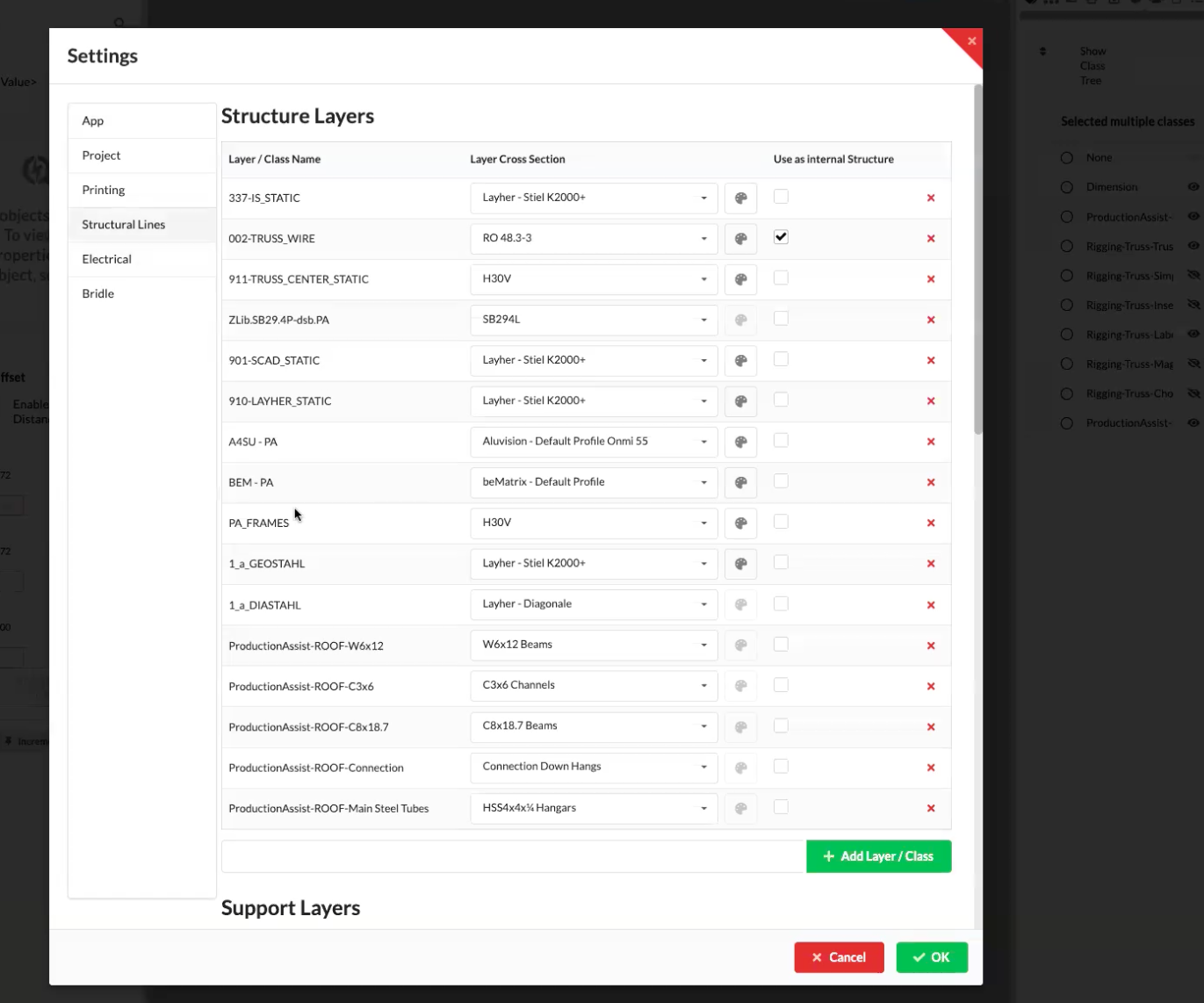
Class names can be chosen freely. What matters is not a particular name, but the correct assignment under Structural Lines.
Drawing the Structure and Supports in the Symbol#
- Open the 2D or 3D component of the Vectorworks symbol for editing.
- Activate the class configured under Structure Layers.
- Draw the centerlines of the load-bearing components.
- At every node, make sure at least one line ends with its endpoint on the other line. Two lines that merely cross are not automatically recognized as connected.
- Activate the class configured under Support Layers.
- Use the point tool to place a point at every actual floor-support position.
- Exit symbol editing.
- After exiting symbol editing, select the affected symbol instances and update them using File > Vectorworks Integration > Update Symbol for Production Assist.... Alternatively, read the Vectorworks drawing again.
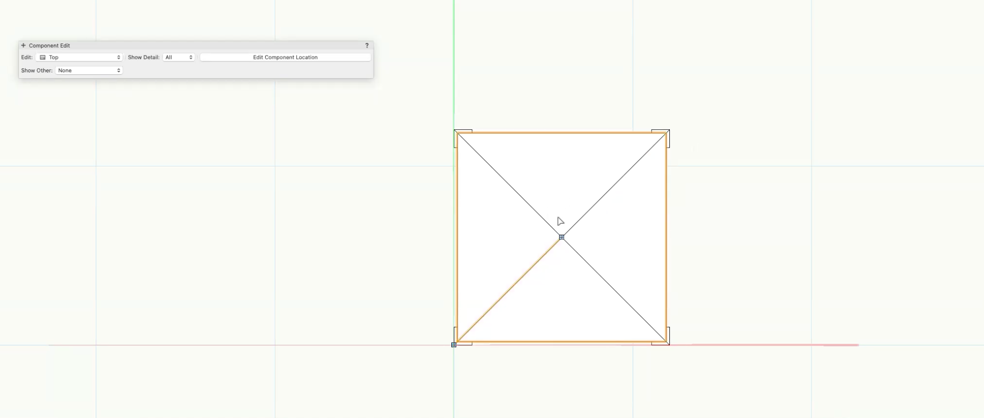
Production Assist creates the calculable structural model from the lines and the ground supports from the points. You can then check the detected structure and support markers in the Renderer.
When reading the drawing, Production Assist also takes Vectorworks symbols nested inside a group into account. The group geometry and the positions of the nested symbols are carried over. After reading the drawing, still check that the structure, supports, and connections are in the expected positions.
Creating the Connection at the Correct Height#
If the truss connection is above the bottom edge of the ballast body, the internal structure must not end only at floor level.
In the 3D component, draw a structural centerline from the lower structural point to the actual connection height. The upper endpoint of this line forms the transfer point to the truss above. After updating, align the truss exactly with this point.
The generated structure does not automatically provide a corresponding Vectorworks snap. If the symbol should snap into place while drawing, add a correctly positioned Magnet geometry to the symbol definition as well.
Choosing a Simplified or Detailed Structural Model#
A single internal line can greatly simplify a ballast body or frame. This is only appropriate if the idealization is technically acceptable for the intended calculation.
If deformation or stability of a real steel frame must be considered, trace its actual members as structural lines and assign the appropriate tube, rectangular tube, or IPE cross sections. Production Assist can then account for the stiffness of these components instead of representing the load path only through a highly simplified substitute model.
Common Errors#
- The visible geometry was adapted, but structure or support elements are missing.
- A support lies at the symbol origin rather than at the actual support point.
- Lines cross without ending at a shared node.
- The structure class has no suitable cross section assigned under Structure Layers.
- Support points lie on a class that is not configured under Support Layers.
- The symbol was not updated or the drawing was not read again after editing.
- The truss above appears to be in the correct position but is not connected to the internal structure.
- A simplified rigid model is used even though deformation of the real frame is relevant to the verification.
Final Check#
Run a structural calculation after every change and use Select System Objects or the deformed shape to check whether the custom symbol really belongs to the expected structural system. Also check self-weight, support reactions, connection heights, cross sections, and possible uplift forces.
Further Information#