

Calculate Ballast determines how much additional weight is needed at the Ground Support supports so that no support lifts off under the active tipping load combination. The command checks multiple wind directions and accounts for a second wind pressure if it is enabled in the load-combination settings. If floor friction is enabled, the horizontal force also affects the calculated ballast requirement.
The calculated value is stored on each support in the model and shown in its label as GroundSupportBallast. Production Assist does not place physical ballast or define a real bearing surface or anchoring. Transfer the displayed mass and position to the setup plan, then check that the ballast can actually be installed there.
Check the model and supports. Compare the drawing with the planned setup. Check that all legs stand on the intended support points and that the supports are connected to the structural system.
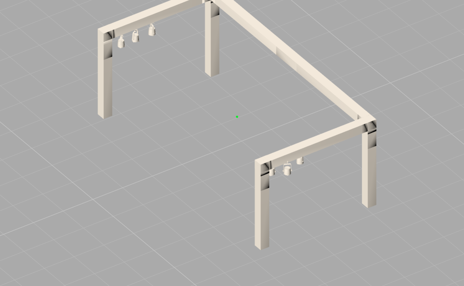
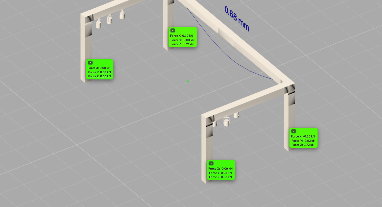
Check support reactions before calculating ballast. The labels show reaction forces in X, Y, and Z. X and Y are the horizontal directions; Z is the vertical direction. A negative Z result indicates that the model requires a downward holding reaction at that point. On a freestanding structure, this can indicate uplift and therefore a risk of tipping.
The blue values 0.66 mm in the second image and 23.85 mm in the third image are deflection indicators. They are neither forces nor ballast masses. A larger deflection indicator does not by itself mean that the structure will tip; check the support reactions and the active tipping load combination.
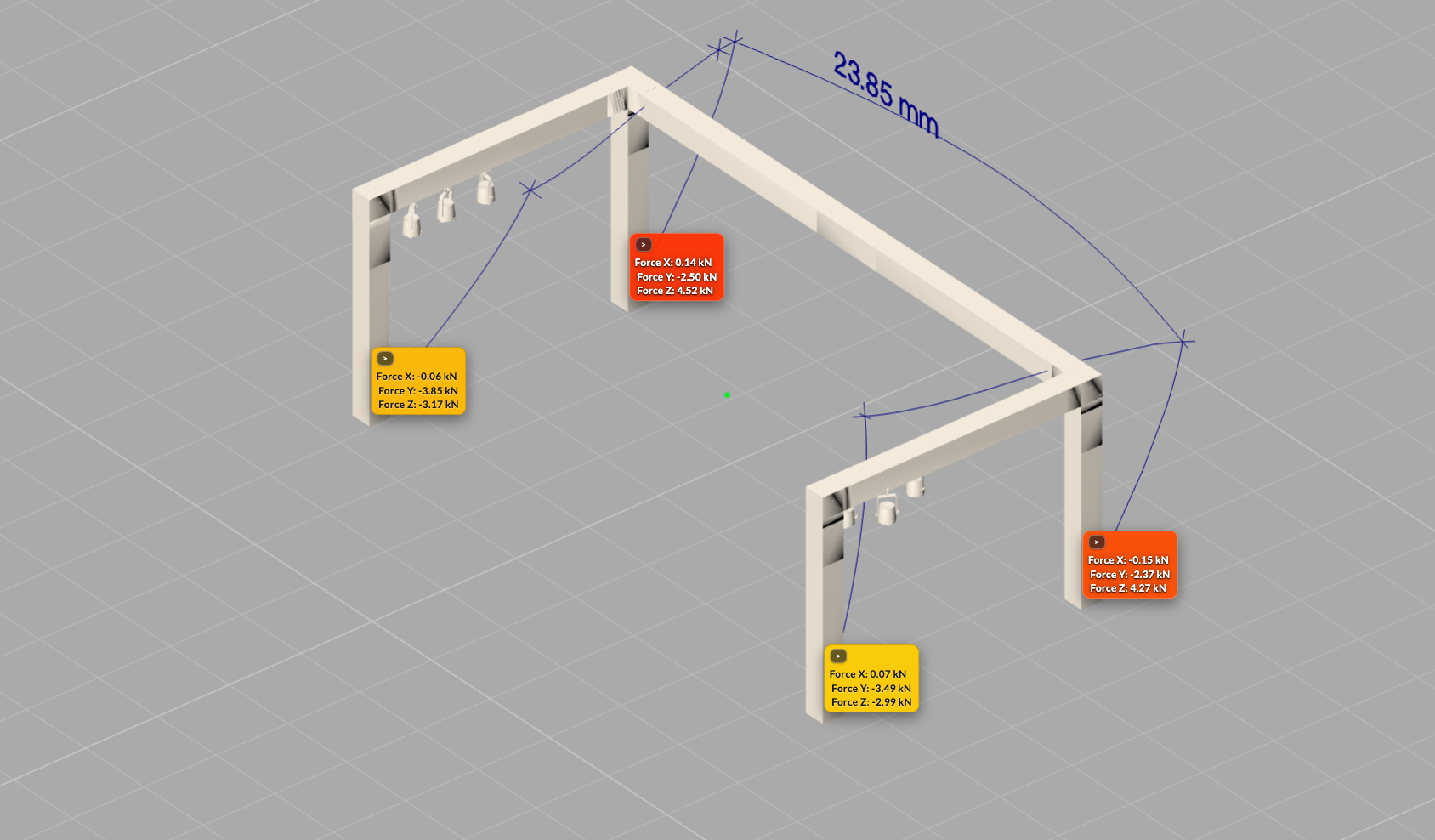
Run the command. Select Rigging → Special Operations → Calculate Ballast. Production Assist calculates the requirement for the Ground Support supports using the active tipping combination, checks multiple wind directions, and uses the highest requirement found for each support. An enabled second wind pressure is also taken into account.
Read the ballast mass and support reactions after the calculation. The GroundSupportBallast label gives the required mass in kilograms. The Force X, Force Y, and Force Z values below it are support reactions; their unit follows the drawing and is kN in the examples.
The fourth screenshot shows these example values:
| Position in Screenshot | GroundSupportBallast | Force Z |
|---|---|---|
| Top left | 363.98 kg | 0.40 kN |
| Top center | 328.86 kg | 7.74 kN |
| Bottom center | 340.92 kg | 0.36 kN |
| Right | 312.60 kg | 7.33 kN |
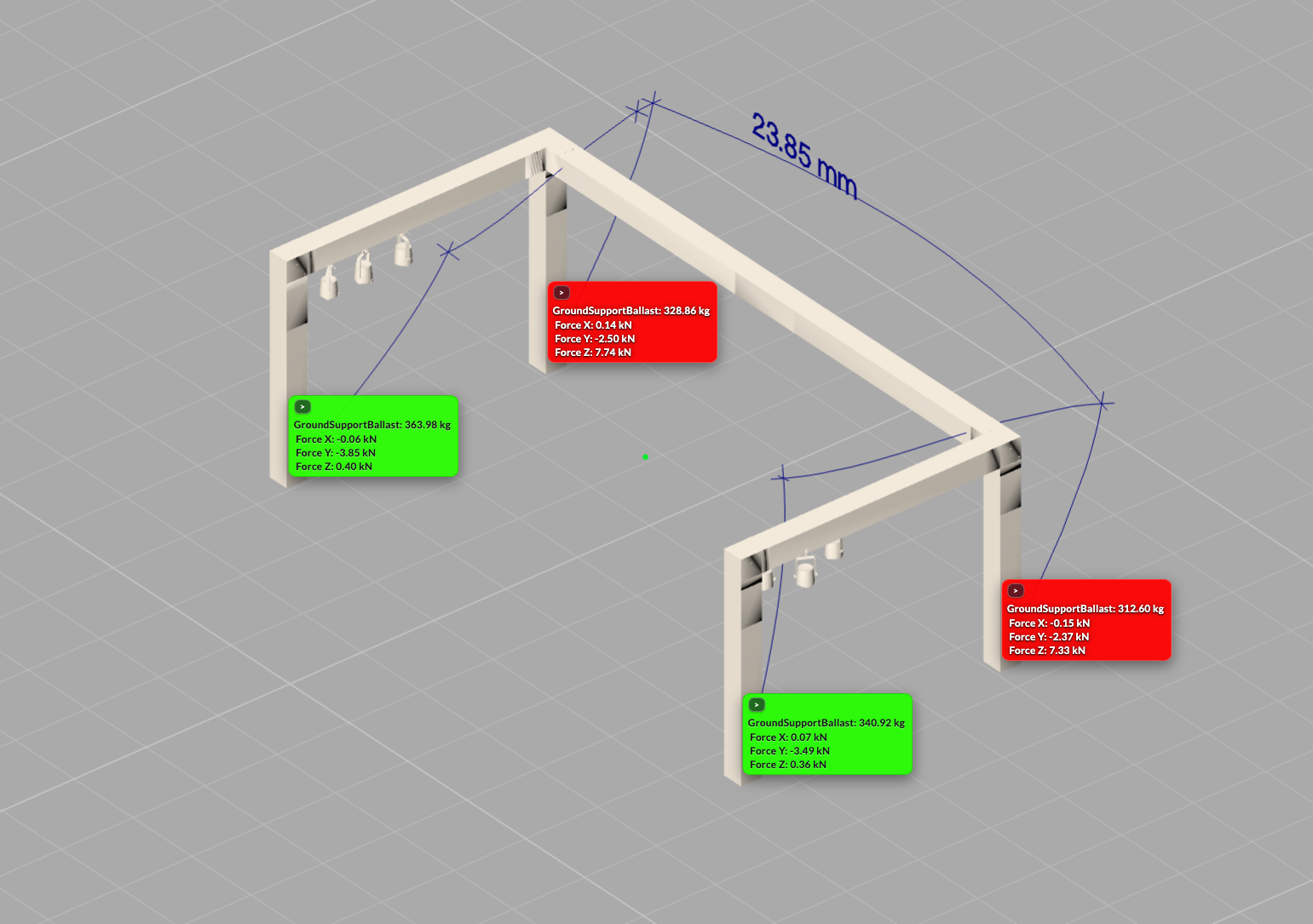
The ballast masses in the fifth screenshot are still example values. The force components have changed in the displayed calculation state; the Z values are 0.22 kN, 7.92 kN, 7.49 kN, and 0.20 kN. The blue dimension 91.49 mm indicates deflection; it is not a ballast mass.
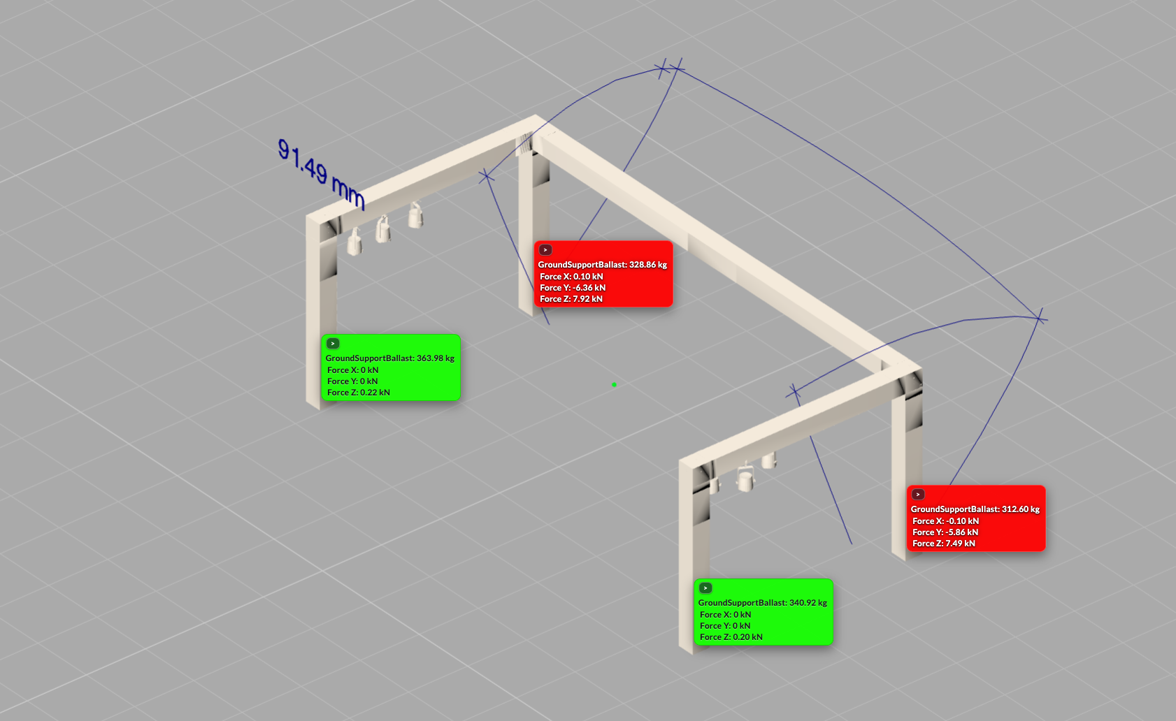
Check the values and recalculate after changes. X, Y, and Z forces do not all have to be zero. The ballast calculation is intended to prevent the governing vertical reaction from becoming negative. With floor friction enabled, it can also add ballast to provide horizontal resistance. If the geometry, loads, wind parameters, supports, or friction change, run Calculate Ballast again.
With Rigging → Special Operations → Reset Ballast for Auto-generated Supports, you reset the saved ballast of all automatically generated Ground Supports in the open drawing to zero. For example, use the command to check the structure again without the additional ballast calculated previously.
You can undo the reset with Undo and apply it again with Redo. After saving and reopening, the ballast remains reset. Calculate Ballast can then generate new ballast values. Resetting in the model does not remove physical ballast and is not approval to set up without ballast.
GroundSupportBallast is a mass in kg. Force X, Force Y, and Force Z are reaction forces, shown in kN in the screenshots.For more information about calculation results, see Static Calculations. For modeling and checking Ground Support, see the Ground Support tutorial.