

The Bridles renderer view shows the two-, three-, and four-leg bridles in the current drawing, along with their dimensions and the parts used. Open Bridles at the top right of the renderer, or select a bridle and click Edit Bridle… in Object Properties. The bridle preview in Object Properties opens the same editor. The controls use the selected application language.
Bridle Builder is a dedicated creation workspace for two- and three-leg systems in the current drawing. In the desktop app, open it using Creation workspace in the footer or Bridle Builder at the top right of the renderer. While the creation view is open, the general toolbar, Scene Tree, navigation, Object Properties, and footer are hidden. Full editor returns to the previous editor layout and renderer view. Choose Create two-leg bridle or Create three-leg bridle, then enter a name, material set, rope definition, load, and drawing coordinates for the connection point and upper attachment points. An optional drop point D is below the connection point. The Builder creates an assembly with actual bridle legs held at their upper ends and an actual load object. Core populates the legs using the selected material set. If suitable material data is missing, the material message remains incomplete; it does not confirm load capacity.
Even when no material set or rope definition is available yet, you can open a template using either creation action and edit its geometry. Create bridle remains disabled until both material details are available. If resources are missing, return using Full editor, provide the material data, and open the Builder again.
In the overview, you can select two- and three-leg systems. Drag the labeled points J, A, B, C, or an existing D directly in Front elevation or Plan. The coordinate not shown in that projection is retained. A second finger cancels the current point drag and leaves the view to the pan or zoom gesture. Alternatively, change the local coordinates in the input fields; they are applied when you confirm the field. Each completed point drag and each confirmed coordinate change is automatically saved in the drawing as a single undoable geometry change. While creating a system, you can also move the points in both projections before Create bridle. In a system without a drop, the load follows the connection point. In a system with a drop, the load stays at point D. If a PA load is at the previous load point, it must match the Builder snapshot unambiguously; if the association is missing or ambiguous, the geometry change is rejected and the current drawing state is reloaded. Bridles without a PA load remain editable. Apply the material set and rope definition using Apply material and allocate parts; Core performs the material assignment and may adjust the resulting geometry to suit the available stock.
In the Inspector, you can also change the mass of the associated load. Confirm the field with Enter or leave it to save the change automatically in the drawing; it is an undo action and then starts a new Core calculation. The Builder allows this input only when it has identified exactly one actual PA load at the connection point or at the end of the drop. If that association is missing or the load was changed outside the Builder, a conflict is reported and the current drawing state is reloaded.
Use Delete bridle system to remove the selected bridle and its unambiguously associated PA load after confirmation. Other objects in the same assembly are retained; if this leaves the assembly empty, the assembly is also removed. Undo restores the deleted objects with their previous UUIDs. If there is no PA load at the bridle target point, only the selected bridle is deleted. If Core detects a load there whose identity or expected state does not match the Builder snapshot unambiguously, deletion is rejected and the current state is reloaded.
As soon as you move a point or confirm a coordinate, Calculation required hides the previous forces. After saving, the Builder automatically starts a new Core calculation; you can also run Calculate to recalculate the current drawing. While a manual calculation is running, further Builder changes are locked. If the drawing nevertheless changes externally, the Builder discards the delayed result and requires a new calculation. Forces are shown only after a calculation has finished for the drawing state that is still current. Drawing diagnostics shows messages for the active drawing, not only those for the selected bridle. An empty message area does not confirm that all checks have passed. Capacity unavailable means that no capacity is available for the component; it is not a passed check. Full editor returns to the previously used renderer view. The full overview and parts editing, including four-leg bridles, remain available under Bridles.
The bridles are listed on the left with their names, object IDs, and number of legs. One bridle shows the selected entry; All bridles shows all entries that are not hidden. Search includes names, object IDs, and assemblies. Use the eye buttons to hide or show entries in this overview.
The selected bridle's settings appear in the middle area above the drawings. Bridle configuration shows the Material set and Steel diameter / rope definition fields, along with the Leg and First leg rope (automatic) selectors. When space is limited, the fields wrap onto multiple rows. Click the header containing the bridle name to collapse or expand the settings and make more room for the drawings. The preview remains visible.
Dimensions, Parts library, Basket parts, and Leg parts are initially collapsed. Open the areas you need to edit; the library and parts lists can be open at the same time. Settings and drawings scroll together. Cancel and Apply changes remain accessible at the bottom. In very narrow views, the bridle list appears above this area.
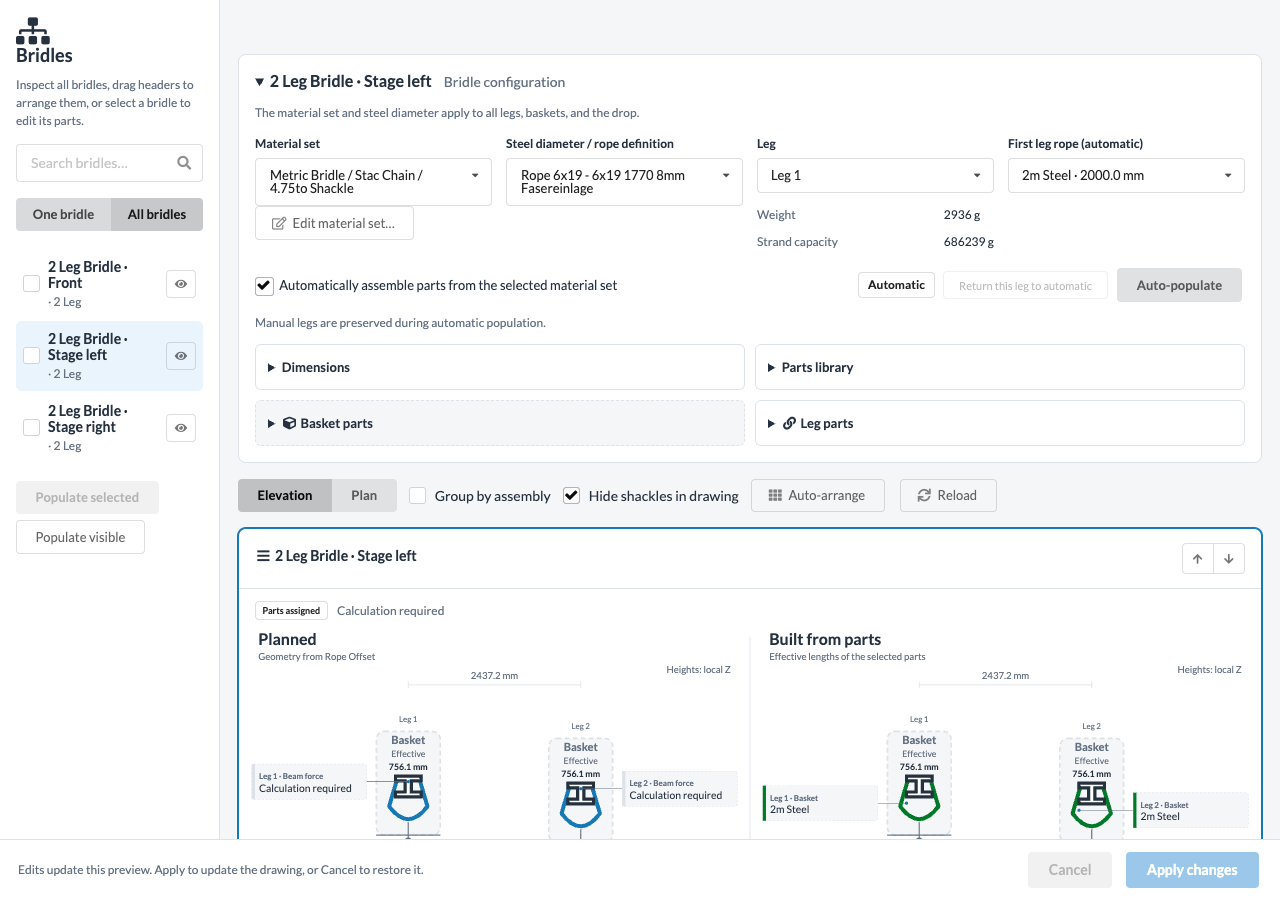
Elevation shows a side projection along the greatest horizontal extent of the attachment points. Plan shows the top view. Lengths and angles refer to the three-dimensional geometry; especially with three or four legs, the projection may look shorter than the stated three-dimensional length. Angles are given relative to the vertical. Lengths and angles use the configured display units.
Each drawing compares Planned with Built from parts at the same scale. Enlarged previews use more height for the legs. Planned shows the planned leg and drop lengths from Rope Offset as dashed lines. Built from parts uses the effective lengths of the parts actually selected, including the basket portions. The assembled connection point is calculated from the effective length of the first leg, vertically above the fixed lower load point. Its height may differ from the plan; the lengths of the other legs do not shift it sideways. Any drop remains vertical in this view. The pale dashed reference shows the original plan there; small rings identify connection parts. The assembly preview does not change the planned geometry.
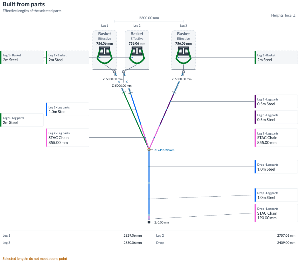
At the upper attachment points, the blue connection point, and any lower load point, the corresponding height is shown as Z: in the configured length unit and precision. Heights: local Z identifies the reference as the bridle object's local coordinate system. Planned shows the planned connection height; Built from parts shows the height calculated from part lengths. These values remain visible in Plan, the compact preview, and the SVG export. If attachment points overlap in projection, different heights remain readable on separate lines.
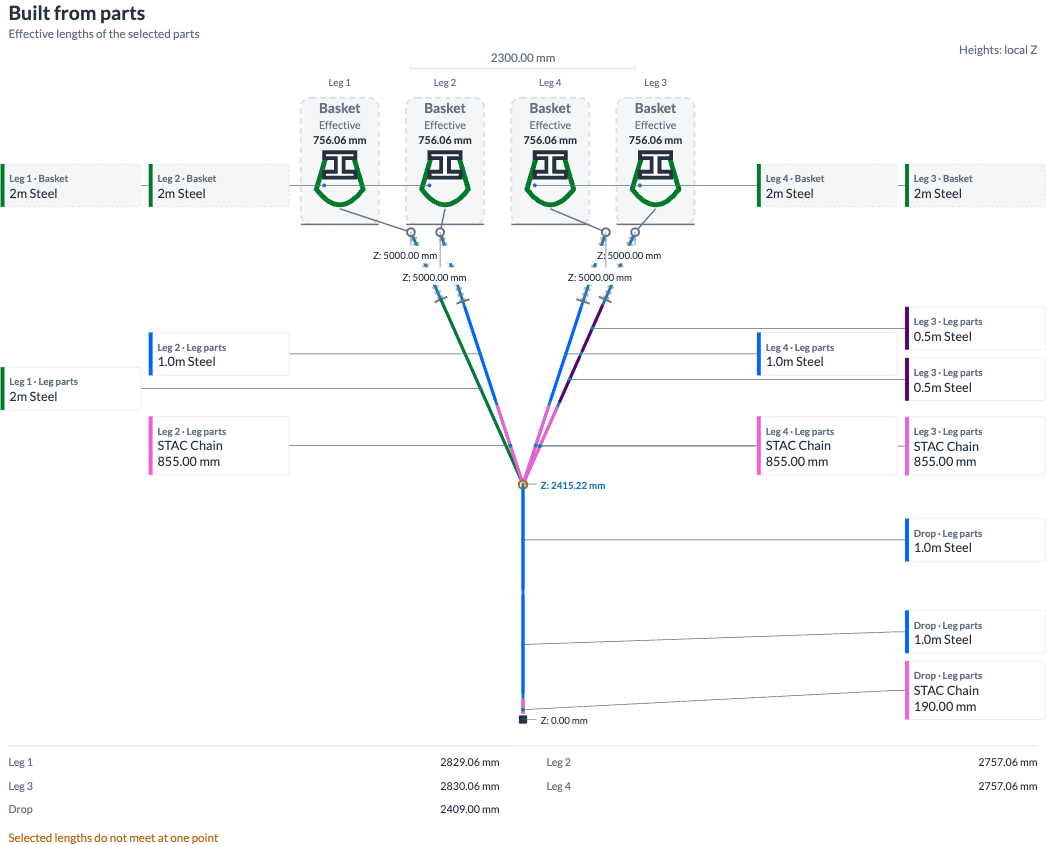
In Built from parts, each selected part name appears directly beside its own rope section, connection part, or basket. A thin leader line shows the precise position of the part. Identical parts used more than once each receive their own label, arranged in parts order. Each label identifies the leg and uses the labels Basket or Leg parts. With three and four upper legs, each leg has its own label column. If two legs are on the same side, their parts appear side by side in two separate columns. Any drop follows in its own area below the rightmost outer leg. This column arrangement also applies to force labels under Planned. The basket is shown at the attachment point as an enlarged, labeled symbol with a frame and a lower divider. Inside the basket frame, Effective gives its calculated effective total length in the configured length unit. This value includes the effective rope portion from the basket dimensions and all assigned basket shackles, even when they are hidden graphically. It appears in Planned, Built from parts, the compact preview, and SVG export. While a parts preview has not yet been calculated, Missing data appears instead of an old or estimated value. The basket drawing is schematic; leg lengths remain at the shared scale. With three and four legs, closely spaced basket symbols are shifted sideways so the frames, parts, and effective lengths remain readable. Their leader lines point to the actual attachment points; model geometry is unchanged. The effective basket portion of the leg is also highlighted with a dashed line, ending at a cross-line marking the start of the leg parts. Basket and leg labels form separate groups with extra spacing. Adjustable parts show their selected length. Long names wrap, and the drawing expands to accommodate extensive labels. Click a part name to edit the corresponding leg. These labels are also included in SVG export.
Use Hide shackles in drawing to hide shackle symbols and their labels in the visible drawings. This option is on by default and also applies to Export drawing…. Shackles remain included in Used parts, Parts by leg, the parts library, and the editable parts lists. Hiding them does not change the selection, quantities, effective lengths, or calculations. Turn the option off to draw the shackles again.
A part's color comes from the Color code of its inventory geometry in the bridle material set. Use Edit material set… next to Material set to change the assignment directly in the bridle dialog. Alternatively, edit the symbol in Resource Manager, select the inventory geometry, and assign an existing color code in Object Properties. The Color Codes list manages names and colors. The bridle view shows the color code name and a color marker in the library and parts lists. Drawing labels show only the part name, its adjustable length if applicable, and its assigned color; the color code name is also omitted there in SVG export. Rope sections, shackles, and basket parts also use the color. Multicolor codes appear as color bands. Changes to a color code also apply to parts already assigned. Without a color code, the existing default colors remain; adjustable leg parts are then shown in ochre.
In the 3D renderer, rope sections of a populated bridle also use the color codes of their assigned parts. The sequence runs from the upper attachment point through the basket parts and leg parts to the connection point; for the drop, it runs from the connection point to the lower load point. Multicolor codes appear as alternating color bands. Section lengths follow the effective part lengths, including the effective basket portion, and are distributed along the existing leg geometry. The basket appears as a section at the upper end of the rope, not as a wrap modeled to scale. This display does not move attachment points.
All 24 components in the three supplied bridle sets receive a color code when they are created. The defaults use more distinct hues and brightness levels: dark purple and red, strong blue and green, yellow-gold, bright orange and magenta, and light turquoise. Matching components in the two metric sets share the same code. Imperial steel ropes also use a white band to distinguish them:
| Metric steel rope | Color | Imperial steel rope | Color |
|---|---|---|---|
| 0.5 m | Purple | 2 ft | Purple / White |
| 1 m | Blue | 5 ft | Blue / White |
| 2 m | Green | 10 ft | Green / White |
| 5 m | Gold | 15 ft | Gold / White |
| 10 m | Orange | 20 ft | Orange / White |
| 20 m | Red | 25 ft | Red / White |
STAC Chain is magenta, Chain Shorten is turquoise, and 4.75t Shackle is slate gray. This assignment also applies when the part is used in the basket. Color codes can still be renamed, recolored, or replaced with other codes. When older standard parts without a saved color-code property are loaded, the default is used. Saved custom assignments and explicitly empty assignments are retained. The palette is set when parts are created. Saved colors and names are loaded unchanged.
If the selected lengths of the other legs or the drop do not meet the connection point determined by the first leg or the fixed lower load point within 1 mm, the actual leg lengths remain visible. Open ends are marked orange and Selected lengths do not meet at one point appears. A manually selected first length that is geometrically impossible also remains as the actual material length, with a visible discrepancy. No assembly geometry appears until parts are available for all upper legs. The preview checks geometric lengths and does not replace a static calculation.
The drawings also show the distance between the pair of attachment points used in the projection and the lengths per leg. When space is limited, the plan and assembly appear one above the other. In the compact view and for two legs, coincident attachment-point labels are combined; in the detailed three- and four-leg views, individual basket symbols and leg labels remain separate. The table continues to list individual legs. Used parts shows the total quantities separately under Basket parts and Leg parts. Parts by leg expands the individual parts in their order, grouped by leg and by the same two areas. Basket parts and Leg parts are also separate areas in the settings above the drawings. Click a leg in the drawing or table to edit its details in the settings.
A manually edited leg is marked Manual. Parts from another set are rejected at the destination. Adjustable parts have an additional length field; only lengths within the specified range that match the part's increment from its minimum length are allowed. Individual lengths are retained when parts are moved or reordered.
Auto-populate creates a parts preview for the selected bridle. Select multiple entries on the left and use Populate selected, or use Populate visible for the drawings currently visible. Each bridle's shared material set must contain suitable ropes and connection parts.
First leg rope (automatic) sets the single rope element for the first leg from the shared material set. The first automatic leg always contains exactly one rope element with its associated connecting shackle; its basket is handled separately. It does not receive an additional chain or a combination of multiple ropes. Automatic lets the system select a suitable single rope length. This selection is available when automatic assembly is enabled and the first leg is automatic.
The effective total length of the first leg, including rope, shackle, and basket, determines the height of the connection point vertically above the fixed lower load point. The required lengths of all other legs and the drop are calculated from this and populated with suitable rope, shackle, and chain parts. If a drop already exists, changing the fixed first rope length also recalculates the height. The upper attachment points and lower load point remain in place. A drop inherits the shared material set and rope cross section; it receives leg parts but no upper basket.
If the fixed first rope is too short for the horizontal distance, or the connection point would be below the load point or above an upper attachment point, the preview is rejected with an error. Select a different first rope length or check the basket dimensions. Without a fixed choice, only geometrically possible single ropes are compared for the first leg.
If the available parts do not match exactly, the best assembly found is shown with the remaining length differences. The difference for each leg and open ends under Built from parts remain visible; a complete parts list does not confirm matching geometry. The first automatic leg matches exactly; unavoidable differences affect the other legs or the drop, for example because of permitted chain length increments. When several assemblies fall within the permitted length difference per leg, the one with fewer parts is preferred; if they use the same number of parts, the smaller length difference decides. For an automatically populated additional leg or drop with a valid adjustable chain, the permitted difference is half the chain increment. In all other cases, it is 1 mm.
Manually assigned parts are retained. A manual leg further along does not prevent the fixed first rope length from recalculating the height; its unchanged parts may then show a visible length difference. If the first leg itself is manual, the planned geometry remains fixed during automatic part assignment. Return this leg to automatic makes the selected leg available for automatic assembly again. The Automatically assemble parts from the selected material set option determines whether automatic legs are reassembled when other changes are made. This can add a drop to a bridle that does not have one. A height that already matches the single first rope length is retained during ongoing part assignment. Auto-populate, Populate selected, or Populate visible compares the choice of single first rope length and the matching parts for the other legs again.
When File → Settings... → App → Use Bridle Material Engine is enabled, Production Assist automatically checks the populated bridle legs, including the drop, against the 3D geometry of other objects in the background. The check uses newly assembled rope paths and manually assigned legs. It also runs when static live calculation is disabled. A dialog preview that has not yet been accepted with Apply changes is not checked.
Under File → Settings... → Bridle → Bridle safety clearance, set the safety clearance from other objects. The default is 100 mm and applies to all bridles in the application. The distance is measured from the straight rope axis to the 3D surface of the other object; reaching the configured distance also counts as a conflict. At 0 mm, only actual collisions are checked. The input uses the configured length unit. Click OK to rerun the check with the new clearance.
If a collision or safety-clearance conflict occurs, the Material Engine first tries to rebuild the bridle at another suitable connection point using the available parts. It accepts only an assembly with sufficient clearance whose leg lengths are within the permitted length difference. The upper attachment points and lower load point remain in place. A fixed first-rope selection, manually assigned parts, and disabled automatic assembly remain binding.
Only if no suitable rebuild with sufficient clearance is possible does Bridle rope collision or insufficient clearance appear in the error list. The entry names the other object and marks an affected position in the model. Move the obstacle or correct the bridle geometry or material selection, then check the updated message. Also check that the configured safety clearance suits the plan. Resolved conflicts disappear at the next background check; disabling the Material Engine removes its collision messages.
The check compares straight rope axes with existing 3D mesh surfaces and also checks rope paths that lie entirely inside closed meshes. Object transformations and nested symbols are taken into account. Objects to which the leg is attached at either end are excluded, even when a safety clearance is configured. Attachments are also identified from structural lines in the model. This exception applies to each leg individually; other obstacles along the rope path are still checked. The bridle's own geometry, explicitly hidden partial geometry, and the first and last millimeter at each rope end are also excluded. An obstacle without a 3D mesh cannot be checked. Rope diameter and the actual wrapping of the basket are not evaluated.
Open Dimensions in the settings above the drawings. It shows the required length, effective assembled length, and their difference, as well as fields for connection and basket dimensions. New basket dimensions start at 0. Previously saved dimensions remain visible even when no material set is selected. The effective length accounts for basket dimensions. When basket width and height are 0, half the length of the folded basket rope plus the assigned shackles is still included. A length difference indicates an assembly discrepancy; a complete parts list does not mean the static calculation is complete.
Change the connection point height in Junction height (local Z). In View, you can also drag the blue connection point vertically under Planned, or, after focusing it, move it in 100 mm increments with the arrow keys. Raising it on a bridle without a drop creates an additional Drop to the previous lower load point. An existing drop is lengthened or shortened accordingly. The upper attachment points and lower load point remain in place; the height is limited to the range between the load point and the lowest upper attachment point. Automatic legs remain automatic, and manual legs retain their parts. When automatic assembly is enabled, the height is adjusted to a geometrically possible single first rope length, and the new drop is also populated. The calculated height may therefore differ from the height you dragged to or entered. While dragging, the height label at the blue point updates immediately. Once the parts preview has been calculated, the drawings show the resulting heights; with automatic adjustment, the calculated height replaces the initial dragged value. Basket height and Basket width apply to the selected leg. Heights refer to the bridle object's local coordinate system.
Parts and geometry are initially edited as a preview. Apply changes applies all pending bridles together; Cancel discards the preview. After relevant changes, the static calculation must be updated. Calculation required and Calculated distinguish the calculation status from Parts assigned or Parts missing.
If a bridle changes while you are editing it, the pending changes are not applied. Reload and discard preview loads the current state and discards the preview. The old preview is discarded when you switch to another drawing. Export drawing… exports the visible bridle drawing as SVG.
For more information about the existing support fields, see Object Properties. The related overview for structural beams is in Beam View.
Under Bridle configuration, Material group and Steel diameter / rope definition appear before the leg selector. Both settings apply together to all legs, basket parts, and any existing or newly added drop in this bridle. The rope list contains the same definitions, with manufacturer and name, as Object Properties. Changing the cross section retains the assigned parts and updates the weight and capacity for the entire bridle. It first changes the preview; Apply changes saves the shared selection for all supports, while Cancel discards it. A missing or explicitly deselected definition does not provide a calculated rope capacity. For older drawings with different settings, choose a shared set or cross section before applying changes. Different set or cross section assignments within a bridle are rejected during checking and applying.
The table and the settings under Leg show Weight and Strand capacity. Under Dimensions, you will find explanations of the calculation basis. Below the table, Total bridle weight is the sum of all assigned parts across all legs, including the basket and drop. Parts by leg and the editable parts lists also show the weight and Component WLL of each individual occurrence. Hidden shackles are also fully included in weight and capacity. When applying with Apply changes, and during automatic part assignment, a fully known material total is saved as Weight on the bridle object. It includes all legs, full basket ropes, chain parts, and shackles, including those in the drop. The preview alone does not change the object weight. Changes to parts or rope cross section update the weight at the next assignment; assigning parts again replaces the value rather than adding to it. If component masses or part assignments are missing, the previous object weight is retained and the bridle view continues to mark the partial total as incomplete. After a weight change, the static calculation must be updated.
Edit the part's inventory geometry in the material set to enter these values:
0 means the mass is calculated from the full selected material length and the rope definition's linear weight. For definitions with material-dependent intrinsic weight, the cross-sectional area and material density are used. For basket ropes, the entire rope length counts, not only its effective height. A shortened chain part retains its fully entered mass.0 uses only the calculated rope value. This is derived from minimum breaking force × Termination efficiency (0–1) ÷ Rope safety factor, converted to a load mass. The editable initial values are 0.9 and 5. Choose them to suit the actual termination and application. The distinction between breaking force, termination efficiency, and safety factor corresponds to the calculation described in the Crosby termination manual; these settings are not a product-specific certification. The parts list shows the factors used for the rope.The generic standard parts receive these editable weights and capacities. The weights are stored as numbers in grams; Notes is empty when they are created. The interface displays them in the configured weight unit:
| Standard part | Weight of complete part in g | Component WLL |
|---|---|---|
| 4.75t Shackle in all three sets | 1,010 | 4,750 kg |
| STAC Chain, metric set | 4,591.878664278215 | 5,400 kg |
| STAC CHAIN, imperial set | 3,020.972805446194 | 5,400 kg |
| Chain Shorten, metric chain-shortener set | 5,680 | 5,300 kg |
The native standard definition 6x19 1770 8mm Fasereinlage contains a linear weight of 0.229 kg/m. This mass also applies to older drawings with this built-in definition. Together with the hardware WLLs, the standard sets therefore provide complete weight and capacity values when a rope definition is selected.
Full chain masses are retained when shortening. Steel ropes retain the mass calculated from the selected diameter and do not receive an independent fixed weight value. Adjust component weight and WLL to match the product actually used. These defaults apply when standard parts are created. Saved weights and capacities are loaded unchanged, even when they are 0. New custom parts do not receive another part's hardware weight default.
Strand capacity is the smallest complete capacity value among all assigned ropes, shackles, chains, and basket parts for that leg. A basket does not automatically double the rope capacity. Leg values are not added into a total WLL; actual load distribution depends on geometry and calculation. Once parts are assigned, the native leg utilization and bridle check also use this component limit instead of a freely entered support capacity. Without assigned parts, the previous support capacity remains authoritative.
Missing component masses cause the known partial total to be marked Incomplete: missing component weights. Missing capacities, a missing rope cross section, or invalid rope factors result in Missing data instead of a complete strand capacity. Therefore, 0 must not be understood as a confirmed hardware weight or unlimited capacity. While a preview has not yet been validated, old material totals or component ratings are not shown as current values. A drop with 1 m of standard 8 mm rope, a full metric STAC chain, and two standard shackles weighs about 6.84 kg.
Force displays are always on for all visible bridles. Under Planned, Beam force appears at the upper basket or attachment point with signed X, Y, and Z components. For attached structural beams, the components refer to their local coordinate system. Rope force shows the calculated rope force on each leg, including any drop. Values use the configured force unit and precision and are also exported to SVG.
The forces belong to the calculated planned geometry. For a leg that has not yet been calculated, or while a parts or geometry preview is open, Calculation required appears instead of force values. Apply changes and update the static calculation to see current forces.
The bridle list follows the drawing's normal object order, which the Scene Tree shows with No Sorting. Drag a bridle header onto another header belonging to the same parent object to reorder the entries. The arrows in the header provide the same ordering without dragging; they are disabled at a boundary between different parent objects. Assembly assignments are retained. Group by assembly groups drawings by assembly; Auto-arrange sorts bridles alphabetically within each parent object. The change is saved immediately in the normal drawing hierarchy, is also visible in the Scene Tree, and can be undone. The attachment points in the model are retained. Cancel applies to the parts and geometry preview, not the already saved object order.
Under Bridle configuration → Material set, select the desired set and open Edit material set…. Apply or discard any open bridle previews first with Apply changes or Cancel. In the set editor, you can change the set name and each part's Geometry name, and assign an existing color code under Color code or remove the assignment. The color marker shows the current selection before saving.
Add geometry adds a new rope part; the trash icon removes an entry. Under Dimensions and component properties, select Steel / rope, Shackle, or Chain / shortener, and enter the complete part length, Weight, and Component WLL. For adjustable parts, enter the minimum and maximum effective lengths and a positive Length increment. The complete length must be within this range. For fixed parts, leave the range and increment at 0. Ropes also provide a safety factor, end-connection efficiency, and Preferred basket rope. Available for assembly disables a part without deleting its geometry from the set. Disabled local parts remain visible in the editor.
New ropes start with a complete length of 1,000 mm, no color code, and 0 for weight and component WLL. Enter suitable values. For ropes, 0 continues to use the bridle's shared rope definition; for other hardware, this leaves weight or capacity missing. Values use the configured display units. The editor manages the bridle inventory geometries created in the set itself. Other geometry types are retained. Edit parts from other included symbols in the source symbol; geometries with child geometries cannot be removed here.
Save material set saves the definition and immediately updates all bridles in the current drawing that use this set, including hidden entries, all legs, baskets, and drops. Names, colors, fixed part lengths, inventory quantities, and complete weight and capacity values follow the changed definition. Automatic legs are assembled again using the available parts; this can change the connection height. Manual legs retain their other parts and planned geometry. Removed or disabled parts are also removed from manual assignments; adjustable lengths are adapted to the valid range and increment if necessary. If the fixed first-rope setting is removed or disabled, it reverts to Automatic. Then check for missing parts and length discrepancies. A set without suitable components is not completed using old assignments. Incomplete weight totals still do not overwrite an existing object weight.
Saving the set and its dependent bridle changes form one undoable action. Force values become invalid; recalculate the statics afterward. Cancel in the set editor discards only its unsaved changes. Changes already saved with Save material set immediately become part of the drawing and are not undone by a later Cancel of the bridle parts preview. If the set changes while you are editing, the draft remains in the editor and saving is rejected. Close and reopen the set editor to load the current version.
Connect your AI assistant to the Production Assist MCP server. The assistant can read the available material sets and bridle assignments with LR_GetBridleWorkspace. A possible instruction is: “In this bridle’s material set, use only the existing 0.5 m, 1 m, and 2 m steel ropes, as well as the existing shackles and STAC Chain. Disable the remaining parts.” Clearly identify the desired set or bridle.
LR_UpdateBridleMaterialSet supports small changes for this purpose under Changes. Teile changes only the specified properties of existing parts, such as Use for their availability, name, color code, or component weight. Unspecified properties and parts are retained. AllowedParts, if needed, contains exactly the existing local component UUIDs that should remain available; an empty list disables all local parts in this set. RemoveParts deletes the explicitly specified components. For new parts, the assistant omits the UUID; the application creates one and returns the complete new set state. The assistant must provide a name and positive length, as well as suitable hardware weights and capacities. Missing hardware data continues to be treated as incomplete. Rope cross-section, factors, and basket behavior work as in the dialog. API lengths use millimeters; weights and capacities use grams.
Set changes affect all bridles that use this material set and form a single undo action. If only one bridle should receive different parts, the assistant edits its assignment with LR_PreviewBridleWorkspace and LR_ApplyBridleWorkspace. The read starting state and the new sequence of parts are passed for this purpose. The material set and rope cross-section must be the same for all legs, including the drop. The preview does not change the drawing. After applying, the assistant reads the workspace state again and checks the result, part assignment, and missing information. The statics must be recalculated before evaluating forces.