

In Production Assist, you can wire/cable network-enabled objects in the plan together and assign addresses to them quickly and easily in the Worksheet.
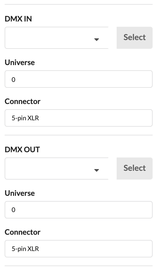
INFO: In order to properly patch spotlights or other network-enabled objects, they should already have a fixture ID. This ID is indicated in front of their name in the Scene Tree. If no such ID is indicated, you can activate the objects, open the Fixture Data area in the Object Properties and assign an ID there.
You can cable network-enabled devices to each other as a daisy chain or with a data distribution box. To do this, you must first insert them into the plan by clicking on New Object in the Toolbar and then to the right on Symbol. The Resources window opens.
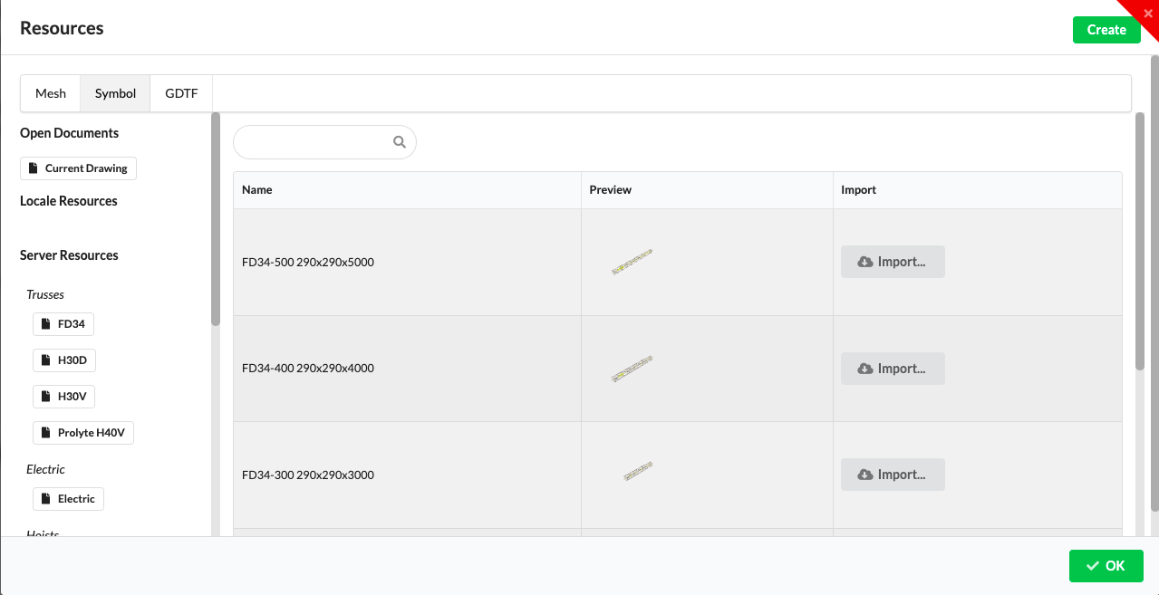
Select the Network library on the left. There you will find data distributors such as DMX splitters, NPUs or switches. Use the grey Import button next to it to insert them into your plan.
Then activate the distributor in the Renderer or Scene Tree and assign an Object ID in the Object Properties.
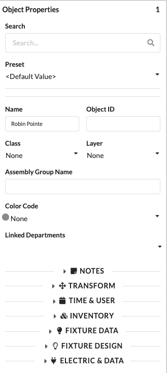
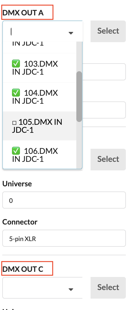
To connect the devices to each other, activate one of the two devices to be connected and open the Electric & Data area in the Object Properties. You will find the field DMX IN for the data input. Click the box to select the appropriate device to connect from the drop-down menu. You can also enter the device name or the FID/Object ID of the desired device in the field to get only these displayed. You can also connect the next device using the DMX OUT field.
If you click on the Select button next to the inputs and outputs, you jump directly to the device connected there and can cable directly.
NOTE: If devices to connect are missing in the drop-down menu, it may be because your program setting only allows patching within the same position/Assembly Group. To change this, go to Settings in the menu bar under File and deactivate Patch Options only for Local Group.
NOTE: The green check mark in front of the name of the input or output in the drop-down menu indicates that this output is already occupied. If you select it anyway, a query comes up as to whether the old connection should be replaced by the one you have chosen.
There are two ways to connect devices to data distributors:
To connect devices to the data distributor, activate the device and open the Electric & Data area in the Object Properties. You will find the field DMX IN for the data input. Click on the field to select the appropriate distributor and output from a drop-down menu. The name of the output is separated by a "." from the name of the distributor. You can also enter the device name or the FID/Object ID of the desired device in the field to get only these displayed.
If you click on the Select button next to the inputs and outputs, you jump directly to the device connected there and can cable directly.
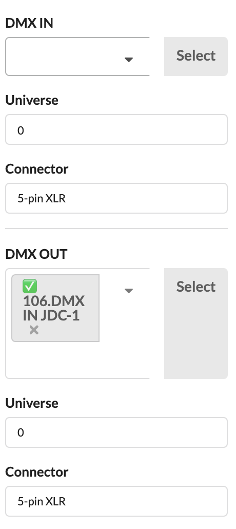
Activate the distributor to which you want to assign devices. Now open the Electric & Data section in the Object Properties. You will find all data outputs there. Click on the field for the corresponding output to select the desired device from a drop-down menu. You can also enter the device name FID/Object ID of the desired device in the field to find it faster.
NOTE: If devices to connect are missing in the drop-down menu, it may be because your program setting only allows patching within the same position/Assembly Group. To change this, go to Settings in the menu bar under File and deactivate Patch Options only for Local Group.
NOTE: The green check mark in front of the name of the input or output in the drop-down menu indicates that this output is already occupied. If you select it anyway, a query comes up as to whether the old connection should be replaced by the one you have chosen.
INFO: In order to be able to patch spotlights properly, they should already have a fixture ID. This ID is indicated in front of their name in the Scene Tree. If no such ID is indicated, you can activate the objects, open the Fixture Data area in the Object Properties and assign an ID there.
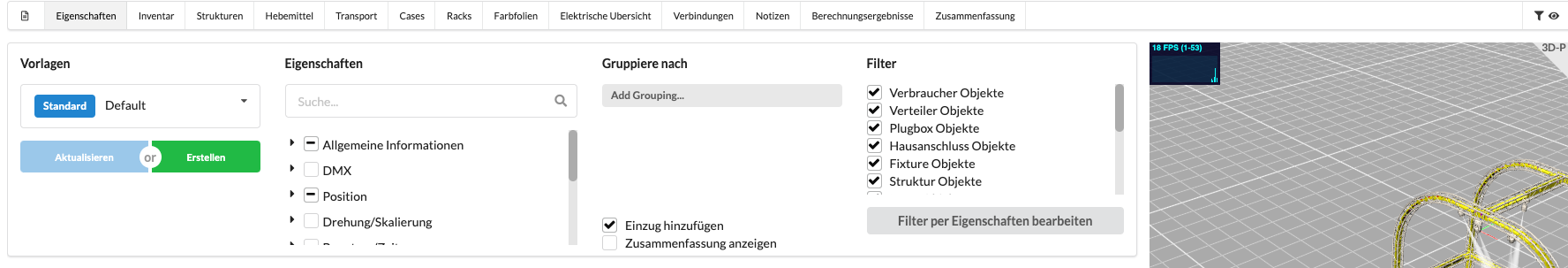
Open the Worksheet window in the menu bar via Window/Worksheet.
It opens with the tabs Properties.
In the upper area you will see the filter area. Under Property Fields you have the possibility to activate individual object properties to display them at the bottom of the worksheet. See Properties Collections for a few predefined property sets on specific topics to enable/disable them more quickly. Under Presets you will find useful sorted compilations of object properties for Paperwork. On the far right, you can also filter whether only objects with certain properties should be displayed in the worksheet.
The columns in the worksheet can be moved by drag & drop and sorted by clicking on them.
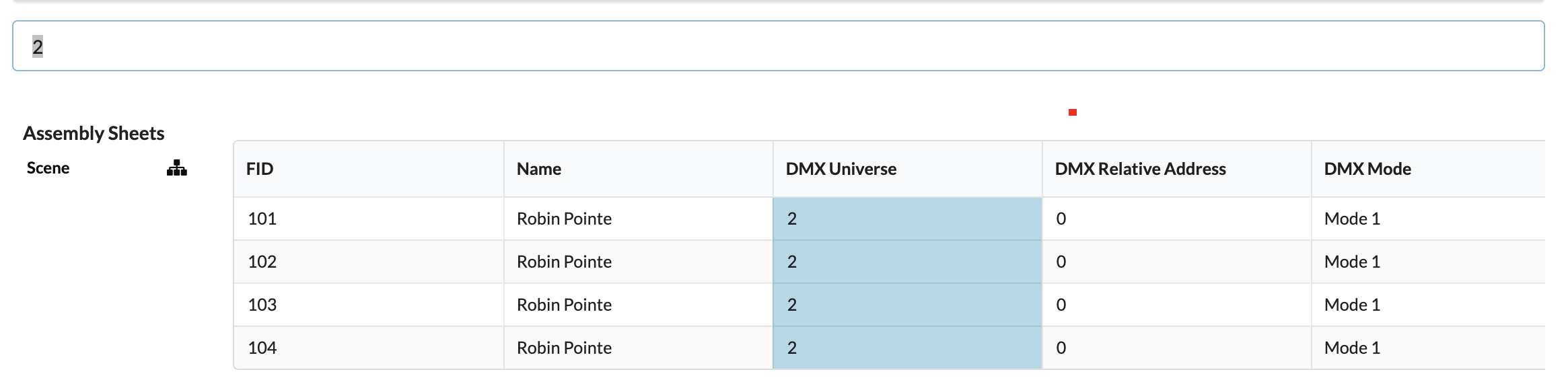
To be able to patch spotlights, activate the Data Patch preset. You select the column DMX-Universe and select the universe field of all spotlights to be patched to the same universe by holding down the mouse button. Now enter the corresponding number and confirm with Enter.
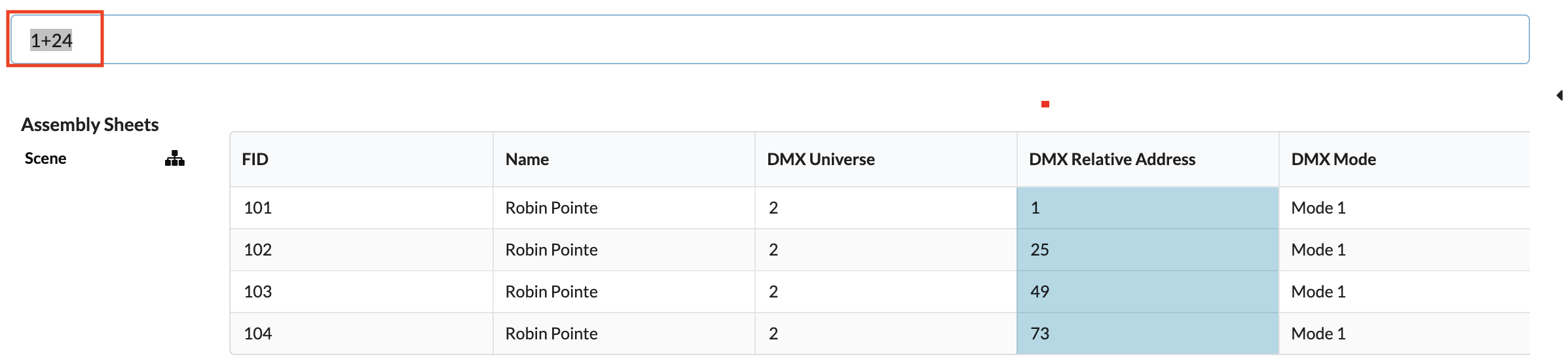
Now look for the column DMX Relative Address, enter the desired address and confirm with Enter. If several spotlights are to be patched one after the other, you can also select several fields by holding the mouse button down, then enter the start address followed by a "+" and the DMX footprint and confirm with Enter.
If you only enter the start address followed by a "+", Production Assist automatically increases the DMX address by the footprint stored in the selected mode.
In the Data Network window you can see which DMX universes are occupied with which spotlights or where addresses are still available.
You can find it in the menu bar under Window.
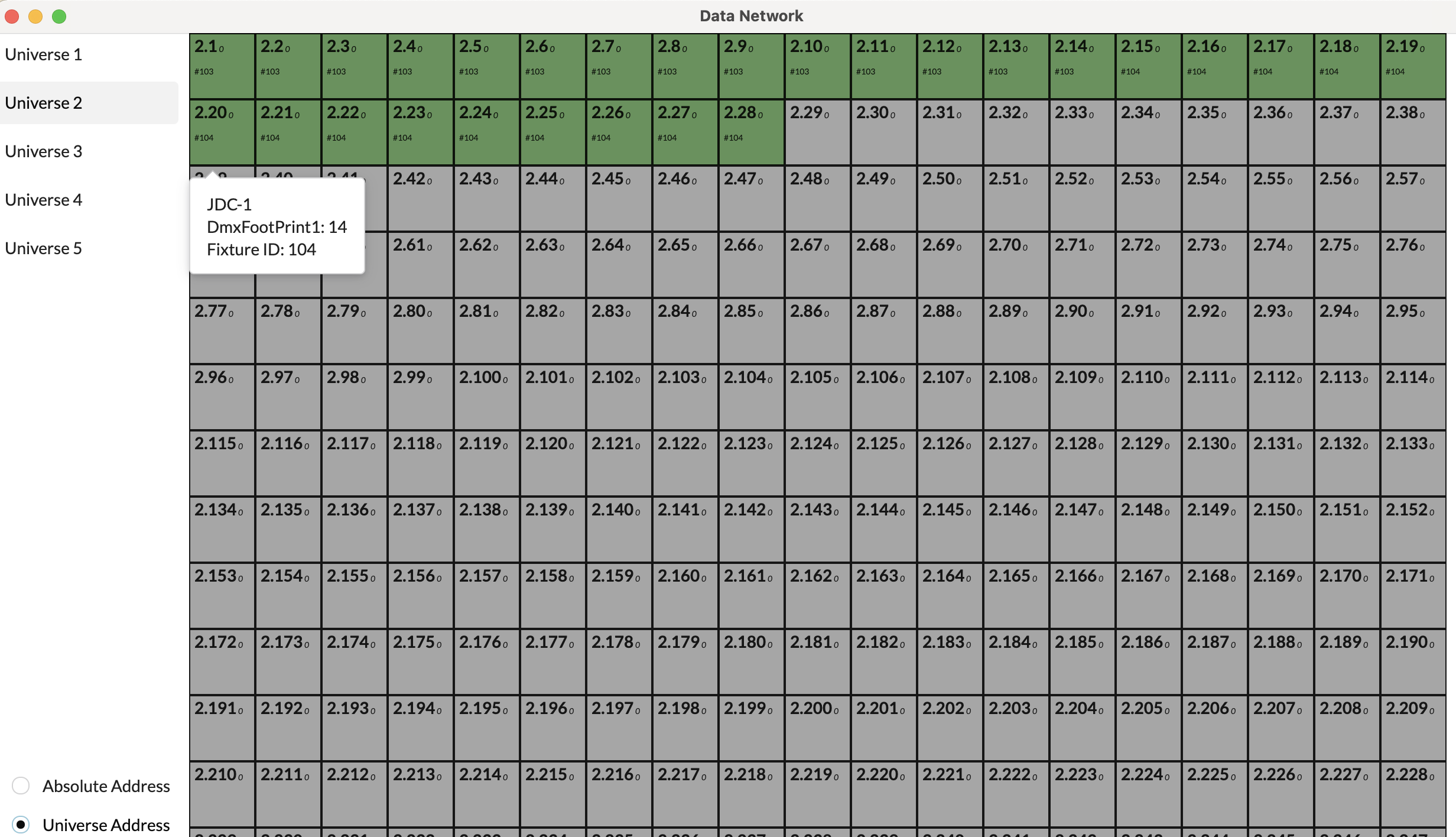
On the left side you can see the universes used. You can either scroll down through the addresses or click directly on a universe to jump there directly.
You can also switch between the absolute addresses or relative addresses view at the bottom.
In the overview on the right, you can see which addresses are assigned which fixture ID. If you hover your mouse over an address, you will also see the name of the fixture and its footprint.