

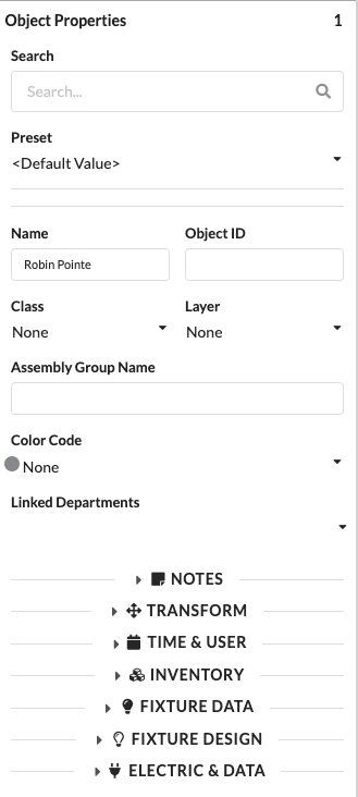
The Object Properties palette displays the properties of the currently selected object. Which fields are visible depends on the selected object type. If multiple objects are selected at the same time, the palette shows the shared or combined properties of this selection.
| Panel/Field | Detailed Description |
|---|---|
| Tab Bar | Shows the available panels of the object properties, for example General, Transform, Inventory, or Electric & Data. Which tabs are displayed depends on the selected object type. |
| Search and Input Panel | In the upper part of the palette, you can directly edit the most important properties of the currently selected object. Depending on the object, this includes name, ID, assignments, and technical parameters. |
| Value Panel | In the middle and lower part, the actual setting fields appear. There you can change properties, review them, or link them to other objects. |
| Object-Dependent Content | The screenshot shows an example view. In your project, more or fewer fields may be visible because Production Assist only shows the properties that are relevant to the selected object type. |
You can use almost all text drop-down menus in the Object Properties as a search field. Click in the field and type a term. Only matching entries will then be displayed. If no entry matches your term, an Add appears in front of it. Press Enter to create this term as a new entry. Typical examples include the drop-down menus for layers or classes.
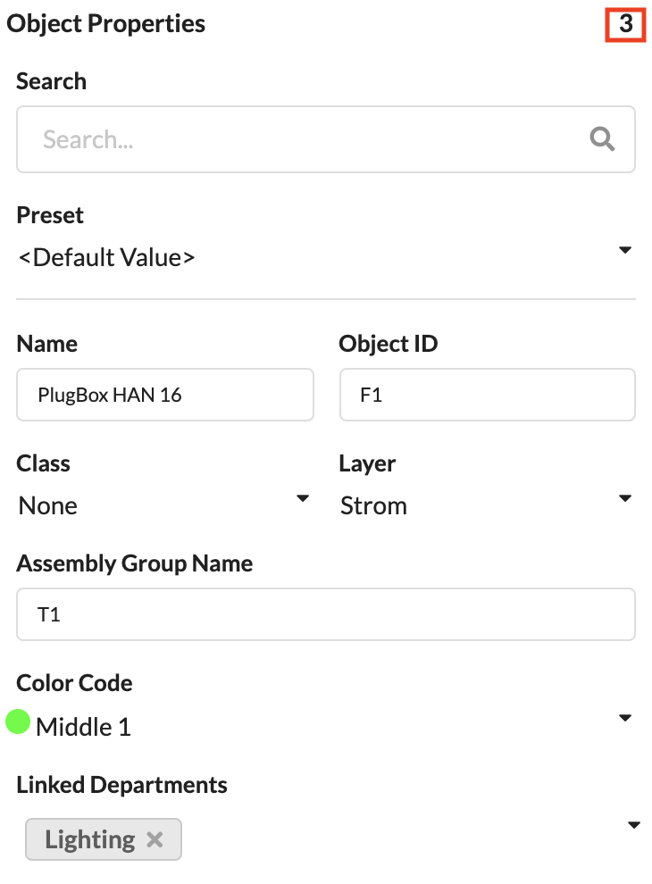
The general information is displayed for all object types. The number in the top right indicates how many objects are currently selected.
The search field allows you to filter the palette for specific properties.
The field shows which preset value currently applies to the object. By default, it shows Default. This means no special preset is being used.
You can learn how to create Presets in the chapter Navigation.
These fields show the Name and the Object ID of the selected object. Both values can also be changed here. The Object ID is always displayed before the Name in the Scene Tree. If it appears in red, it has been assigned more than once in the plan.
These fields show which layer and which class the object belongs to. Both values can be changed here. The class and layer structure is primarily used for working in the drawing, as it controls, among other things, the visibility of objects in the Navigation.
Shows the name of the assembly group in which the object is located.
Here you can assign a Color Code to objects or assembly groups for the Paperwork. This is primarily used in touring productions.
Each object can be assigned a Department for later Paperwork.
| Panel/Field | Detailed Description |
|---|---|
| Search | Filters the displayed properties within the palette. This is particularly helpful when many fields are visible and you want to quickly jump to a specific property. |
| Preset | Shows which preset value currently applies to the object. By default, it shows Default; this means no special preset is being used. |
| Name | Sets the visible name of the object. This name appears later in lists, in the Scene Tree, and in the Paperwork. |
| Object ID | Shows or changes the unique identifier of the object. It is primarily used for unique assignment and stands out immediately in the Scene Tree if it has been assigned more than once. |
| Class | Assigns the object to a class. This is mainly used to control visibility, structure, and filters in the drawing. |
| Layer | Assigns the object to a layer. This is important for organizing objects cleanly in larger projects. |
| Assembly Group Name | Shows or changes the name of the assembly group to which the object belongs. This helps with logically grouping related objects. |
| Position | Stores a free position designation for lists, labels, and Paperwork. Here you can enter, for example, a descriptive mounting or deployment position. |
| Notes | Stores internal notes directly on the object. This information helps with handovers, special cases, or team inquiries. |
| Color Code | Color-marks objects for planning and Paperwork. This allows you to quickly identify, for example, tour segments, responsibilities, or object groups. |
| Linked Departments | Assigns the object to one or more departments. This makes it clear which team or work area is relevant for the object. |
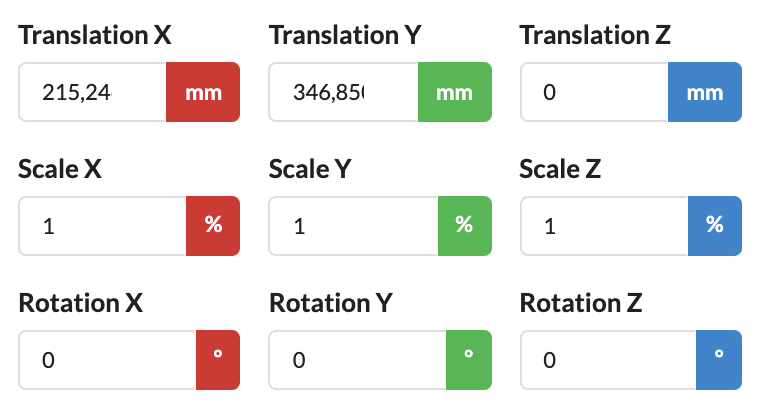
The Transform panel contains all information about the position, scaling, and rotation of the object. The units are color-coded according to their respective axis.
Note: Whether you want to display global or local coordinates is set in the Settings.
With global transformation, the values refer to the parent coordinate system of the project. With local transformation, the values refer to the coordinate system of the object or its parent object. This is particularly important when an object is part of a rotated or moved structure.
| Panel/Field | Detailed Description |
|---|---|
| X, Y, Z | Determine the exact position of the object along the three axes. This allows you to move the object precisely in space. |
| Scale X, Scale Y, Scale Z | Scale the object along the X, Y, and Z axes. These fields are useful when an object needs to be adjusted or mirrored. |
| Rotation X, Rotation Y, Rotation Z | Rotate the object around the respective axis. This allows you to align an object exactly at the desired position. |
| Origin Reference | Defines from which reference point the position offset is calculated. This allows objects to be measured and correctly positioned via defined reference points. |
| PosiStageNet Send Value | Activates the output of position data via PosiStageNet. This option is only relevant when Production Assist is working as a sender. |
| PosiStageNet ID | Shows the PSN ID of the object. When Production Assist is used as a client, this value can be used or set; when Production Assist is sending, the ID is assigned automatically. |
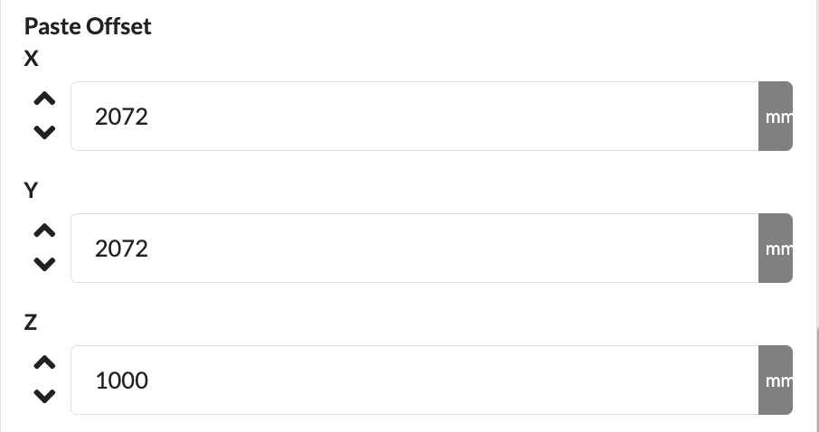
With Paste Offset, you define by what distance copied objects are offset when pasting. This function is especially useful when you want to quickly copy and paste objects with an offset using the keyboard shortcuts Cmd + W, Cmd + A, Cmd + S, and Cmd + D.
| Panel/Field | Detailed Description |
|---|---|
| Paste Offset X | Defines by how much objects are offset in the X direction when pasting. This is helpful when you want to place copies neatly side by side. |
| Paste Offset Y | Defines by how much objects are offset in the Y direction when pasting. This allows you to stagger repeated paste operations in a planned manner. |
| Paste Offset Z | Defines by how much objects are offset in the Z direction when pasting. This is especially useful when you want to paste objects stacked or at different heights. |
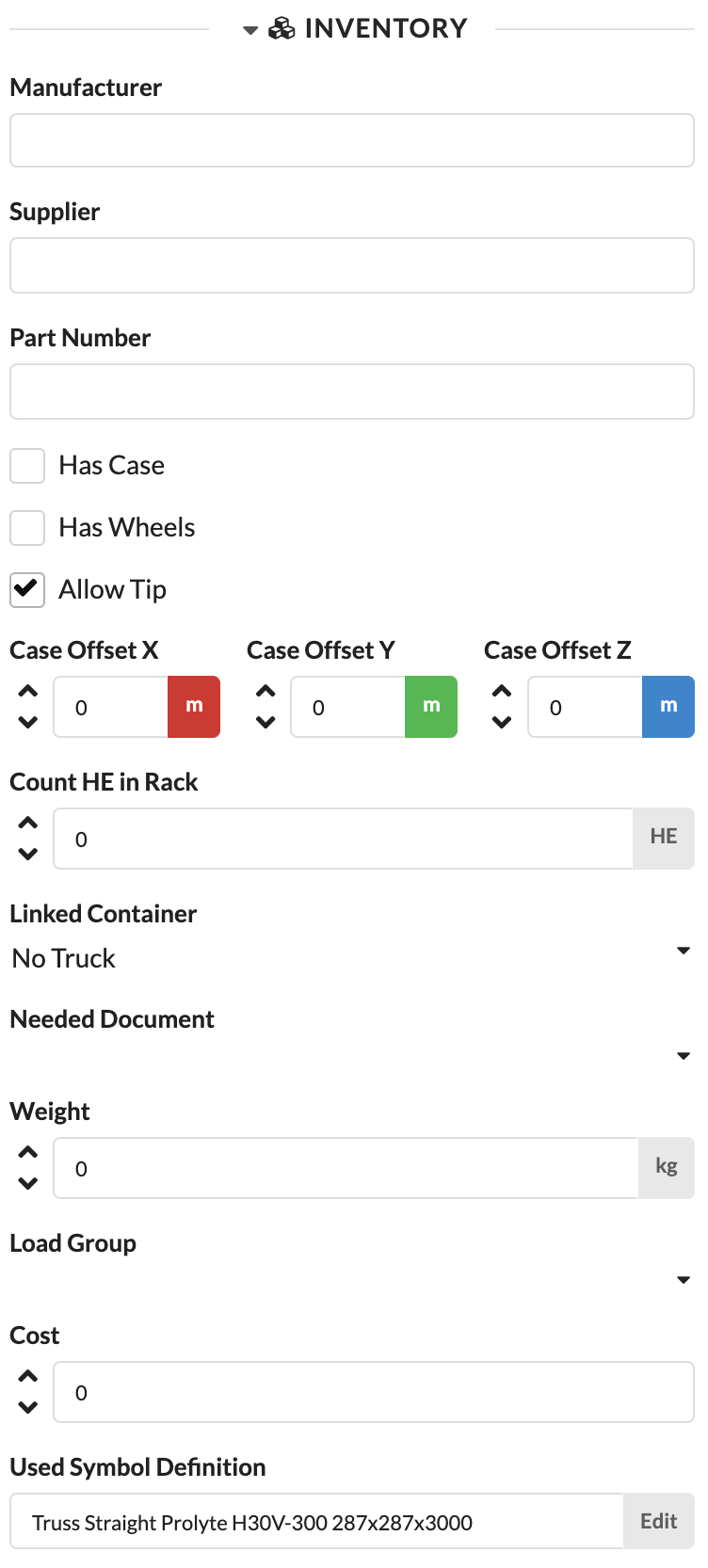
The Inventory panel contains all parameters that are important for logistics.
| Panel/Field | Detailed Description |
|---|---|
| Manufacturer | Stores the manufacturer of the object. This field helps to later evaluate material by brand or origin. |
| Supplier | Stores the supplier of the object. This allows you to track from whom the material was sourced. |
| Purpose | Describes the intended use of the object. This is useful when an object should be categorized not only by its name but also by its function. |
| Part Number | Stores the article or part number. This makes it easier to match objects with warehouse or ERP data. |
| Required Document | Links inspection reports, certificates, or other documents to the object. This keeps important records directly accessible at the relevant entry. Such documents can, for example, be imported as PDF in the Resource Manager. |
| CO2 Footprint | Stores the CO2 value of the object for sustainability reporting. This field supports later ecological reports or comparisons. |
| Costs | Stores the cost value of the object. This allows material values and budget information to be maintained on a per-project basis. |
| Used Symbol Definition | Shows the currently used symbol definition and allows its editing. This lets you quickly check which symbol or geometry is being used. |
| Exists | Marks the object as present and active in calculations and display. This allows you to selectively hide objects or exclude them from calculations without deleting them. |
You can store the manufacturer (Manufacturer), supplier (Supplier), and item numbers from your own merchandise management system (Part Number) to later filter by them in the Paperwork.
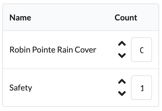
For GDTFs, you can define whether Rain Cover is needed and how many Safetys are required. These will later appear in the inventory list.
| Panel/Field | Detailed Description |
|---|---|
| Rain Cover | Specifies whether a rain cover is needed for the object. This information is later included in inventory lists or Paperwork. |
| Safety | Specifies whether and how many additional safetys are needed. This supports complete material planning for the production. |
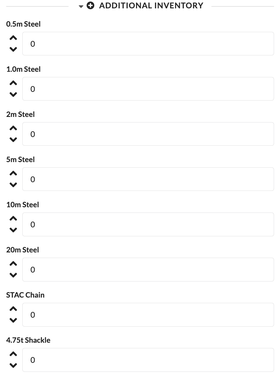
With Additional Inventory, you can assign additional loose parts or accessories to an object.
| Panel/Field | Detailed Description |
|---|---|
| 0.5m Steel to 20m Steel | Records additional steel parts in the specified lengths that are included with or assigned to the object. This allows you to document accessories that are not placed as separate objects in the plan. |
| STAC Chain | Records additional STAC chains for the object. This ensures that loose accessories are also included in material lists. |
| 4.75t Shackle | Records additional shackles rated at 4.75 t. This information is helpful to ensure that all necessary rigging accessories appear in the Paperwork. |
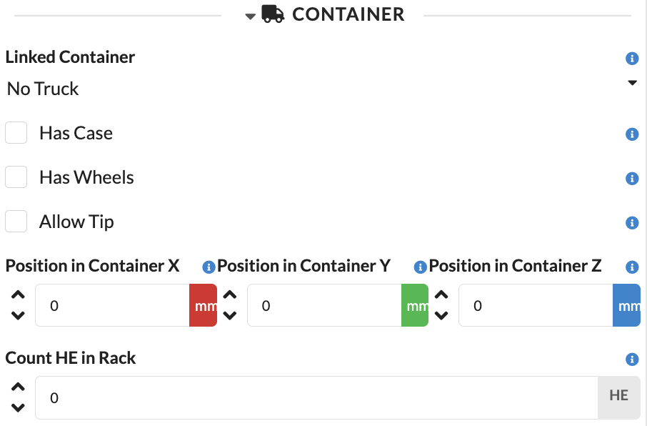
Additionally, important information for truck planning can be stored here, for example pack size, rack height, or the truck, case, or rack into which an object is packed.
There are four different ways to pack objects:
Under Linked Container, you can select all trucks, cases, and racks that were previously created in the Navigation.
| Panel/Field | Detailed Description |
|---|---|
| Linked Container | Specifies in which truck, case, or rack the object is planned. This directly integrates the object into the transport planning. |
| Case | Indicates that the object has its own case. This tells Production Assist that the object should be treated not as a loose item but as a packed unit. |
| Has Wheels | Indicates that the object or case has casters. This can affect packing logic, handling, and space requirements. |
| Allow Tip? | Allows the object to be tipped during packing or loading. This information is important when material may or may not be transported in a rotated position. |
| Position in Container X, Y, Z | Show the calculated position of the object within the container. This allows you to see where the object is placed in the packing volume. |
| Count HE in Rack | Defines the required rack units in the rack. This is especially important when devices need to be properly planned in 19-inch racks. |
To pack an object in a rack, it must first be assigned a rack height. To pack it in a case, the case must still have enough free slots for this object.
Generates a packing volume from the bounding box of the object and unlocks the Case Size and Case Rotation parameters.
Adds the height of casters to the packing volume.
Allows the object to be tipped or rotated during truck planning.
Shows the automatically calculated position of the object within the container in the X, Y, and Z directions.
Defines the size of the packing volume of the object.
Shows the automatically calculated rotation of the case or object within the container.
Defines the height of the object in a rack.
Here you can store important documents such as customs papers or inspection reports. These must first be uploaded in the Menubar under File/Import Document.
The field shows the weight of the object. If the value is set to 0 and the selected objects contain structural geometry, Production Assist automatically adjusts the value based on this geometry.
Additionally, the object properties in the Inventory panel contain parameters for load calculation. On the one hand, the weight of the object (Weight) is decisive here as well; on the other hand, it can be assigned to an existing load group (Load Group). Load groups must have been previously created in the Navigation.
Via the Costs field, you can directly record the costs for the selected object. This allows material values and merchandise management data to be maintained within the project.
Under Used Symbol Definition or Used Mesh for GDTFs, you will find the name of the currently used symbol or geometry for the selected object. For symbols, clicking Edit next to it allows you to edit the symbol definition.
More on the topic of symbol creation and editing can be found in the chapter Symbol Workflow.

Each object in the drawing receives its own QR code, which can also be printed on labels. This allows you to retrieve stored information and the most current object properties at any time.
| Panel/Field | Detailed Description |
|---|---|
| QR Code | The QR code is uniquely linked to the object. When scanned, the stored object information can be quickly accessed, for example for setup, inspection, or service. |
| Object Reference | The screenshot shows that each object receives its own code. This allows information to be retrieved directly at the material without having to search in the plan first. |
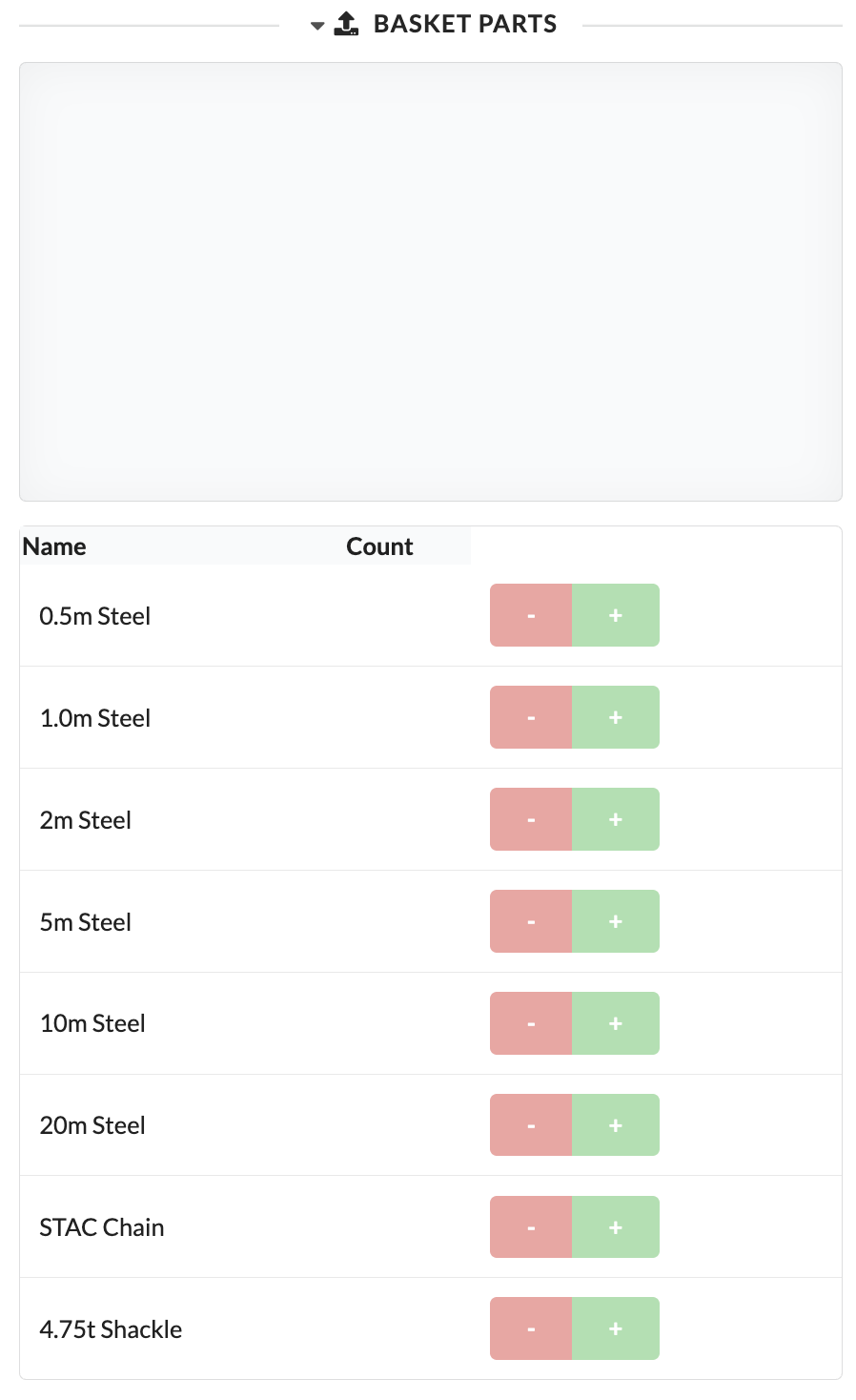
In the Basket Parts panel, you can directly count matching individual parts for a basket or parts assembly.
| Panel/Field | Detailed Description |
|---|---|
| Name | Shows the available basket components in the list. This allows you to see directly which parts can be considered for the basket or assembly. |
| Count | Increases or decreases the quantity of the respective component. This allows accessories to be assembled to match the object and output accordingly. |
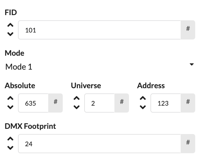
Fixture Data contains all parameters related to the data planning of fixtures.
| Panel/Field | Detailed Description |
|---|---|
| Fixture ID | Shows the numerical identifier of the fixture. It is used for unique assignment, appears in the Scene Tree, and is used so that the fixture can be uniquely addressed on a lighting console. |
| Mode | Sets the operating mode used by the fixture. This determines which functions and how many DMX channels the device uses. |
| Footprint | Shows the number of occupied DMX channels. This value is usually automatically derived from the selected mode. |
| Absolute | Shows the absolute DMX address across all universes. This makes it easier to check larger patches. |
| Universe | Sets the DMX universe in which the fixture is patched. |
| Address | Sets the start address of the fixture within the selected universe. |
The Fixture ID is equivalent to the Object ID for fixtures and is therefore displayed before the name in the Scene Tree. If it appears in red, it has been assigned more than once in the plan.
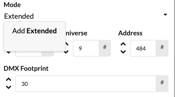
Select the appropriate mode under Mode. The number of required DMX channels (Footprint) will adjust automatically. If your mode does not yet exist, you can create it by clicking in the Mode field and entering the name of the new mode. An Add will then appear in front of it, and pressing Enter opens the Mode Window.
| Panel/Field | Detailed Description |
|---|---|
| Mode Input | Here you enter a new mode name if the appropriate mode is not yet in the list. |
| Add Hint | The screenshot shows that Production Assist can create new entries directly from the search field. This way, you don't have to leave the panel to add missing modes. |
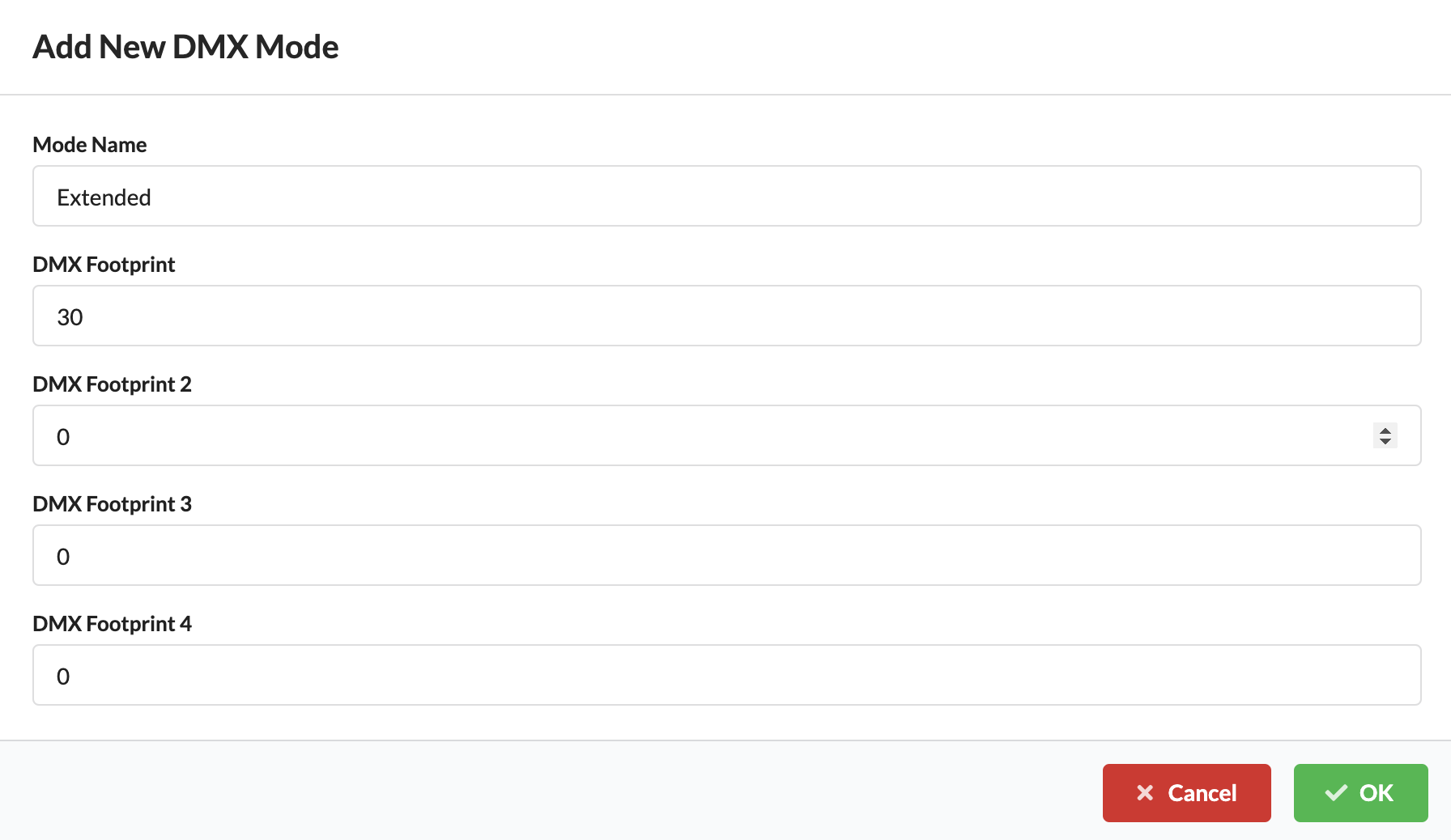
There you can enter the name and the DMX footprint. It is also possible to enter multiple footprints for fixtures that support this.
| Dialog/Field | Detailed Description |
|---|---|
| Name | Sets the name of the newly created mode. This name will then appear in the mode selection of the fixture. |
| Footprint | Defines how many DMX channels the mode occupies. This ensures the addressing of the fixture is calculated correctly. |
| Additional Footprints | If a device supports multiple footprint variants, they can be entered here as well. |
Finally, under Universe and Address, you can enter the DMX address of the fixture. It is automatically displayed under Absolute as an absolute address.
You can find more ways to patch fixtures in the tutorial Create power and network patch documentation..
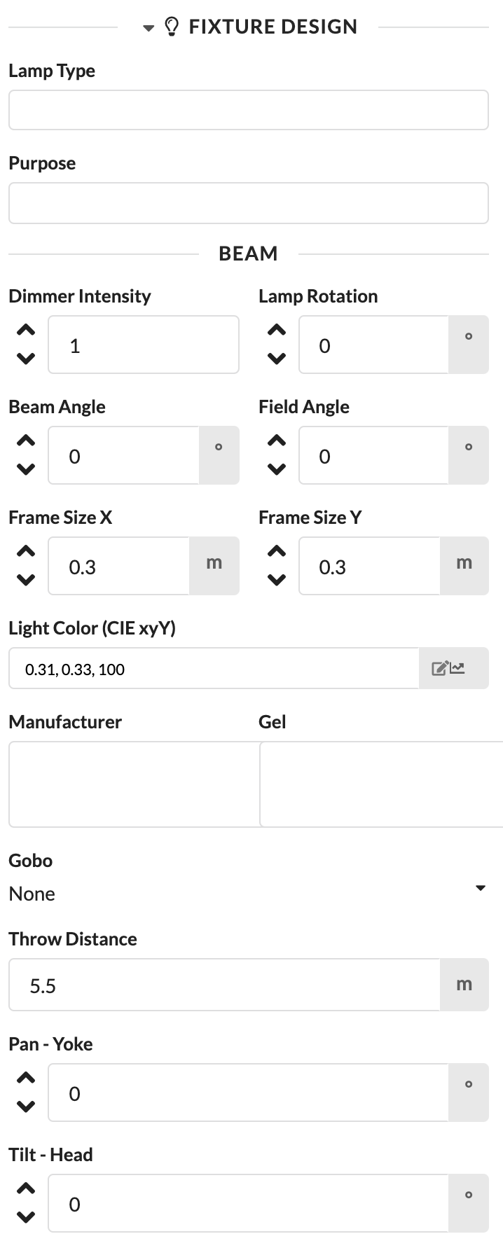
Fixture Design contains all parameters that are important for lighting design.
| Panel/Field | Detailed Description |
|---|---|
| Lamp Type | Shows or defines the lamp type for the fixture. This information is also used later in the Paperwork. |
| Purpose | Describes what the fixture is used for, for example keylight, backlight, or effect. |
| Dimmer Intensity | Controls the brightness of the light output in the rendering. This allows you to visually adjust the effect of the fixture. |
| Lamp Rotation | Rotates the representation of the fixture, for example from hanging to standing. |
| Beam Angle / Field Angle | Determine the size and opening of the light cone. This allows you to better match the light effect in the rendering to reality. |
| Frame Size | Stores the required frame size for Paperwork and accessories planning. |
| Light Color | Shows the set light color and opens the color dialog if needed. |
| Filter / Gobo / Pan / Tilt | In this panel, you will find additional design parameters that control the appearance and orientation of the fixture in the rendering. |
If the fixture is a simple symbol, the only option is to enter the lamp type for later Paperwork.
If the fixture is a GDTF, additional parameters are displayed that are automatically filled in by the GDTF but can also be changed. They always affect the appearance of the fixture in the renderer.
Entering the intended use of the lamp primarily serves the later Paperwork.
Here you control the light output of the fixture in the rendering. For this, Show Beam in 3D must be enabled in the Menubar under File/Settings.
Via lamp rotation, hanging fixtures can be turned into standing fixtures with a rotation of 180°.
These two fields control the size of the light cone.
The frame size is used in later Paperwork to determine the number of required gel cuts and rolls.
Here you can change the color of the beam. Click the pencil icon to do so. The Pick A Color Window opens. The color picker is based on the CIE standard color system. You can set a color in four different ways:
There is a quick select for the colors black and white.
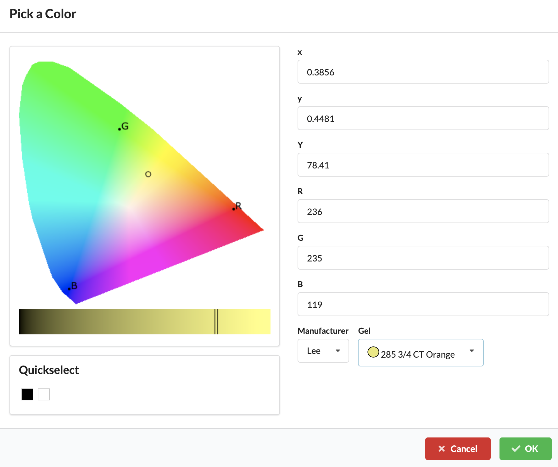
| Dialog/Field | Detailed Description |
|---|---|
| Color Field | Here you visually select the desired color. The field helps you quickly find a matching color impression. |
| Brightness Slider | Use the slider to adjust the brightness of the selected color. This allows you to make the same hue lighter or darker. |
| CIE Values | In these fields, color coordinates in the CIE color system can be entered precisely. This is particularly helpful for standardized or reproducible colors. |
| RGB Values | Here you can set the color via numerical RGB values. This is practical when exact screen or CI colors need to be adopted. |
| Gel Selection | Allows the selection of a manufacturer and a specific color gel. This lets you incorporate real filter materials directly into the planning. |
| Quick Select Black/White | Provides a quick selection for black and white without having to enter the values manually. |
After confirming with OK, both the beam in the renderer and the Light Color field are colored with the corresponding color. The field also displays the color space coordinates.
Via the varying arrow icon, color gradients can be assigned to multiple fixtures. The Set Property Window opens with the two tabs Distribute and Alternate.
With the second editing icon, the settings on the respective fixture (of the assigned object) can be made in the set properties. The setting options Distribute and Alternate are available here. You can select two colors each, between which the beam colors of the selected fixtures are then distributed (distribute) or alternated (alternate).
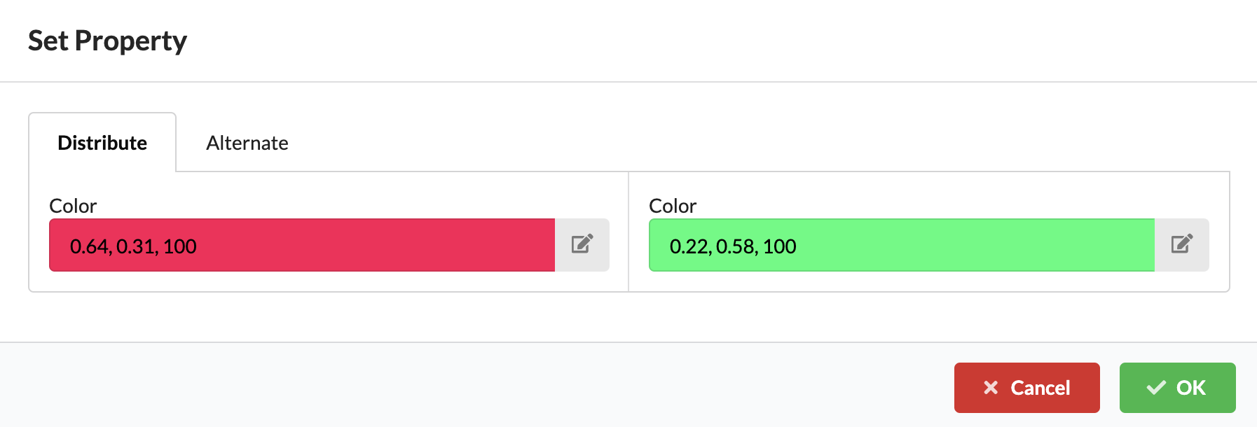
| Dialog/Field | Detailed Description |
|---|---|
| Distribute | Distributes two selected colors across multiple selected fixtures. This is useful for uniform color gradients across a group. |
| Alternate | Alternates the selected colors across the marked fixtures. This creates repeating color change patterns. |
| Color Selection | For both modes, two colors are defined between which distribution or alternation takes place. |
| Property Distribution Preview | The screenshot shows the property distribution window, which allows multiple fixtures to be designed consistently in one step. |
Via Manufacturer, you can select a gel manufacturer, and via Gel, the appropriate filter gel. This is used in later Paperwork to determine the number of required gel cuts and rolls.
If gobos are stored in the GDTF, they can be selected here. They are then visible in the renderer.
Shows the height of the fixture in the space, i.e., at which height it is hanging.
Via Pan and Tilt, the fixture can be rotated and tilted in the renderer.
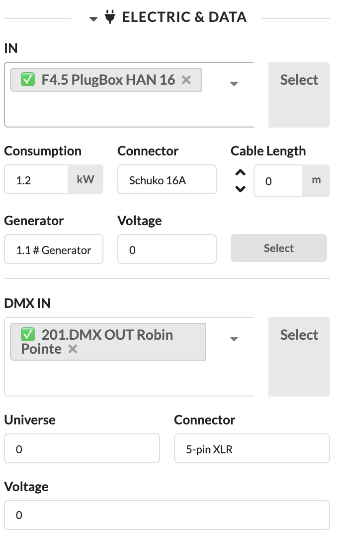
This section appears when your selected object has electrical or network-based connections. Here, cabling for both power and data is planned.
The first section deals with the power connection. Here you will find the inputs and outputs of the selected object with their connection types (Connector) and see the required power (Consumption). Once the cabling is complete, the main connection through which power is supplied is also displayed. Additionally, you can enter a cable length for the Paperwork.
| Panel/Field | Detailed Description |
|---|---|
| Mark as Fully Connected | Marks all connections of the object as fully connected, even if connections are still free. This is useful for marking placeholders as completed (green) and using open connections later. |
| Preliminary Mains Connection | Sets a preferred power source for the object. This allows the later power feed to be prepared and the power load to be determined before the object is fully patched. |
| Input | Shows the input or outputs of the object. Here you can directly see which connections can be patched or checked. |
| More Info Button | Shows additional detail information for the respective connection. There you will find technical values, phase information, and cable details. |
| Patch Field | Used to specify the device or connection to patch to. The field also supports searching via input. |
| Select Button | Jumps directly to the selected counterpart or distributor. This is practical if you want to continue the cabling there. |
To connect the selected object with another device:
Devices that are already wired are indicated by a green checkmark before their name. If you select one of them, you will be asked whether you want to replace the existing connection.
After a successful selection, the connection is linked to the selected counterpart. You can tell by the entry being applied in the patch field, and you can jump directly to the connected object via Select.
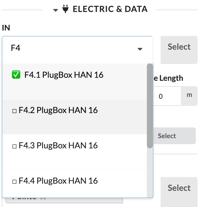
| Panel/Field | Detailed Description |
|---|---|
| Patch List | The screenshot shows the list of available connections on a consumer. Here you select from which distributor or connection the object should receive power. |
| Search Field | By typing in the panel, you can find available connections faster. This saves time, especially in large projects with many distributors. |
| Status Indicator | Already patched devices are identified by the indicator before the name. This lets you immediately see whether a connection is already occupied. |
Note: If you only want distributors in the same Assembly Group to be displayed, enable Patch Options Only For Local Group in the Menubar under Settings.
If you prefer to define the power distribution for the following fixtures directly via a distributor (e.g., the selected plugbox), you can either activate the distributor in the Scene Tree or — if you just connected a fixture to it — click Select next to the drop-down menu. You will then go directly to the selected distributor and can select the desired fixtures for the remaining free outputs.
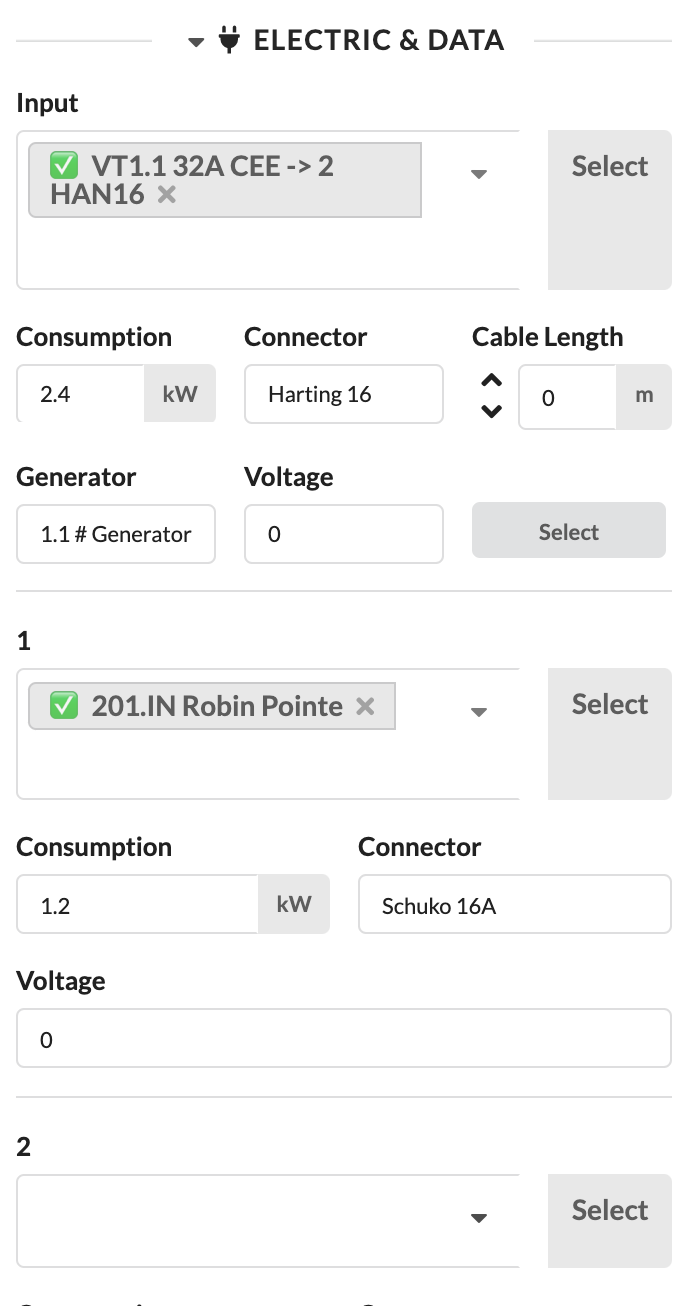
| Panel/Field | Detailed Description |
|---|---|
| Output List | The screenshot shows the opened panel at the distributor. Here you define which consumer is connected to which output. |
| Occupied and Free Outputs | You can directly see which outputs are still free and which are already in use. This makes it easier to distribute consumers cleanly. |
| Continue Working at Distributor | This view is particularly helpful when multiple subsequent devices need to be patched to the same distributor one after another. |
The additional panels help you technically verify power connections and plan cables accordingly.
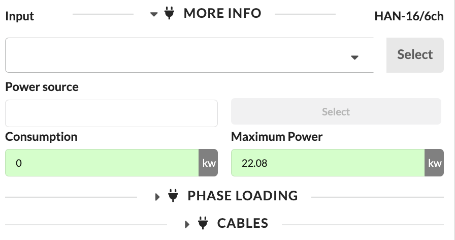
| Panel/Field | Detailed Description |
|---|---|
| Input | Shows the currently viewed input. This clarifies which connection the following detail values refer to. |
| Power Source | Shows the assigned power source for this connection. This allows you to quickly check from which supply the object is being fed. |
| Power Consumption | Shows the current power consumption of the object. This value helps you assess the actual load. |
| Maximum Power | Shows the maximum available or permissible power at this connection. This reveals whether there is still reserve capacity. |
| Phase Loading | Opens the load distribution across phases. This is important for identifying imbalances or overloads early. |
| Cable Planning Panel | Opens the cable planning for this connection. There you can check which cable lengths and cable types are required. |
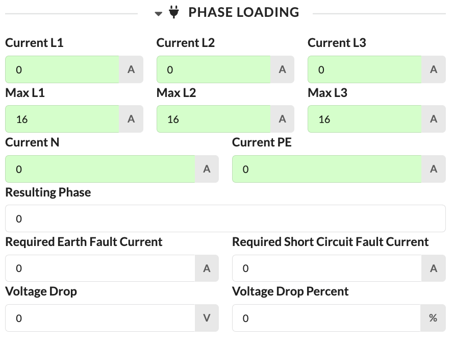
| Panel/Field | Detailed Description |
|---|---|
| Current L1, Current L2, Current L3 | Show the current draw per phase. This allows you to see how evenly the load is distributed across the three phases. |
| Maximum L1, Maximum L2, Maximum L3 | Show the maximum permissible current draw per phase. These values help you avoid overloads. |
| Current N | Shows the current on the neutral conductor. This value is important when asymmetric loads occur. |
| Current PE | Shows the current on the protective earth conductor. This display primarily serves technical inspection. |
| Resulting Phase | Shows the resulting phase image or phase assignment. This allows you to assess the overall situation of the connection more quickly. |
| Required Earth Fault Current | Shows the required earth fault current for the protection. This value supports the technical evaluation of the connection. |
| Required Short Circuit Current | Shows the required short circuit current for the design. This value also serves the technical verification of the power supply. |
| Voltage Drop | Shows the voltage drop in volts. This reveals whether relevant losses arise from cable lengths or loading. |
| Voltage Drop in Percent | Shows the voltage drop in percent. This makes comparison with permissible limit values easier. |
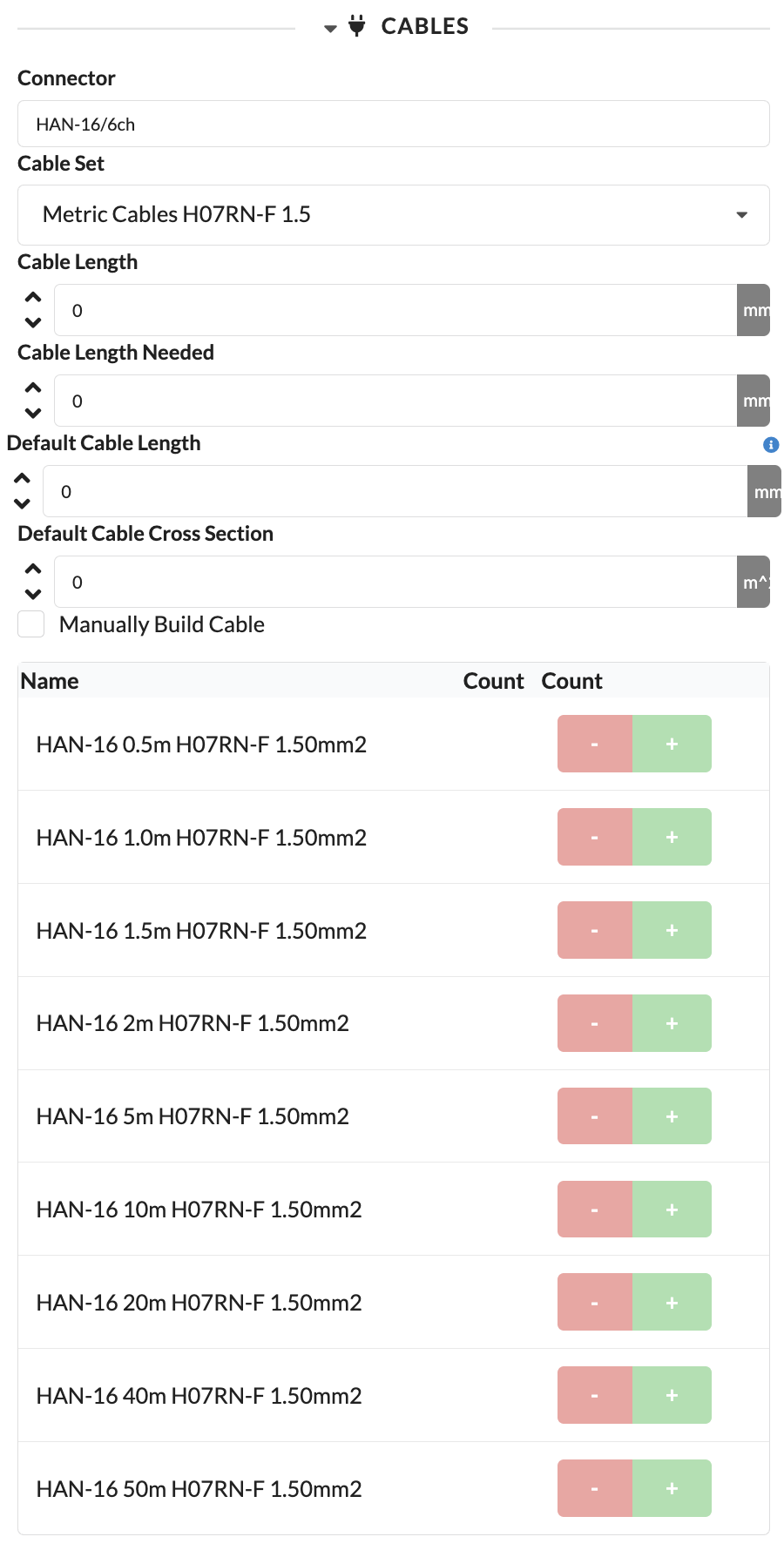
| Panel/Field | Detailed Description |
|---|---|
| Connector Type | Shows the connector type used for the connection. This immediately clarifies which cables are technically compatible. |
| Cable Set | Selects the cable set from which the matching cables are drawn. This is helpful when you work with different cable stocks or standards. |
| Cable Length | Shows the cable length assigned for this connection. This value is automatically generated and serves as the planning basis for the connection. |
| Required Cable Length | Shows the automatically calculated required cable length. It is derived from the ideal distance between the devices along the cable path. |
| Default Cable Length | Sets the default cable length for automatic assignments. This makes cable planning faster for recurring cases. |
| Default Cable Cross-Section | Sets the default cross-section of the cable. This is important for technical suitability and voltage drop. |
| Assemble Cable Manually | Activates manual cable assembly. This allows you to deviate from the automatic logic when needed. |
| Name | Shows the available cable types in the list. This list serves as a selection for the specific cable assembly. |
| Count | Increases or decreases the quantity of the respective cable type. This allows you to specify exactly which cable combination should be output. |
The second section deals with data distribution. Here you will find the available data inputs and outputs, the distributed universe at this connection, and the connection type.
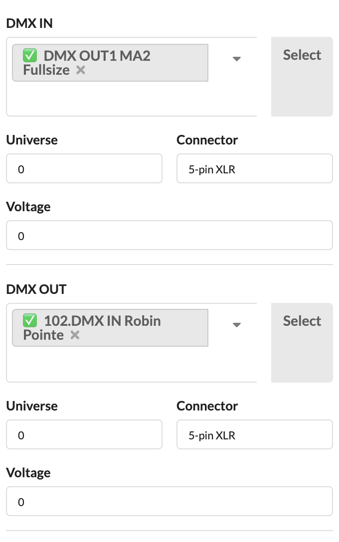
| Panel/Field | Detailed Description |
|---|---|
| Data Input / Data Output | Shows the available data connections of the selected object. Here you plan how data is routed into or through the object. |
| Universe Display | Shows which universe is distributed or expected at this connection. This helps with checking the data structure. |
| Patch Field | Via this field, you link the data connection to another device or distributor. |
| Select Button | Jumps directly to the linked counterpart so you can continue working on the data path there. |
To connect the selected object with another device:
Devices that are already wired are indicated by a green checkmark before their name. If you select one of them, you will be asked whether you want to replace the existing connection.
After a successful selection, the data connection is linked to the selected counterpart. You can tell by the entry being applied in the patch field, and you can jump directly to the connected object via Select.
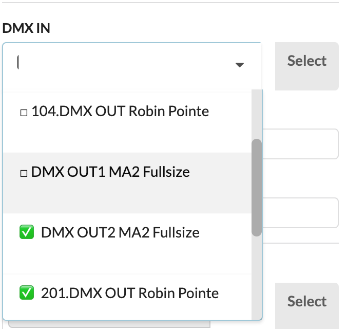
| Panel/Field | Detailed Description |
|---|---|
| Patch List | The screenshot shows the list of available data sources on a device that receives data. Here you define from which distributor or device the signal comes. |
| Search Field | By typing in the field, you can find matching data sources faster. This is particularly helpful when there are many available connections. |
| Status Indicator | Already occupied or connected entries are marked. This prevents accidental double assignments. |
Note: If you only want distributors in the same Assembly Group to be displayed, enable Patch Options Only For Local Group in the Menubar under Settings.
If you prefer to define the data distribution for the following fixtures directly via a distributor (e.g., the selected databox), you can either activate the distributor in the Scene Tree or — if you just connected a fixture to it — click Select next to the drop-down menu. You will then go directly to the selected distributor and can select the desired fixtures for the remaining free outputs.
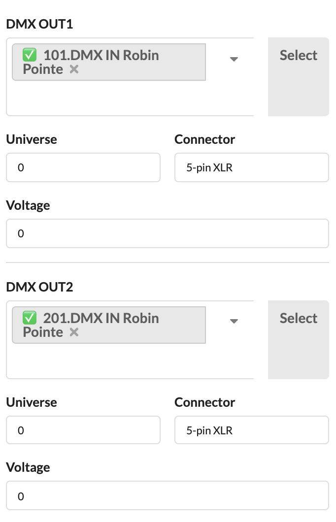
| Panel/Field | Detailed Description |
|---|---|
| Output List | The screenshot shows the opened panel from the perspective of a data distributor. Here you assign outputs directly to the subsequent devices. |
| Occupied and Free Data Paths | You can immediately see which outputs are still available and which are already in use. |
| Continue Working at Distributor | This view is particularly useful when you are routing multiple devices to the same data distributor one after another. |
With Hotpatch, you can specifically optimize the phase loading of distributors. You reassign various outputs of a distributor in a patch field on the object. This allows you to balance the load distribution in the patch more quickly.

| Panel/Field | Detailed Description |
|---|---|
| Hotpatch | Opens the hotpatch function to reassign outputs of a distributor and improve phase loading. This is helpful when you want to balance existing patches without rebuilding the complete setup. |
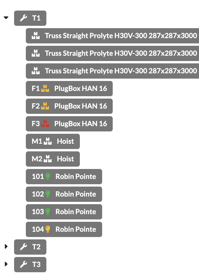
For objects with electrical or network-based connections such as fixtures, power connections, power distributors, or consoles, the color of the icon changes depending on how many connections are occupied:
| Color | Meaning |
|---|---|
| Red | all inputs/outputs are still unpatched/free |
| Yellow | some inputs/outputs are already patched/connected |
| Green | all inputs/outputs are patched/connected |
| Panel/Field | Detailed Description |
|---|---|
| Colored Icon in Scene Tree | The icon before the object name shows the current patch status. This allows you to see in the tree view whether an object is still open, partially connected, or fully patched. |
| Assembly Group View | The screenshot shows that this status can also be quickly checked within assembly groups. This means you don't have to open each object individually to find open connections. |
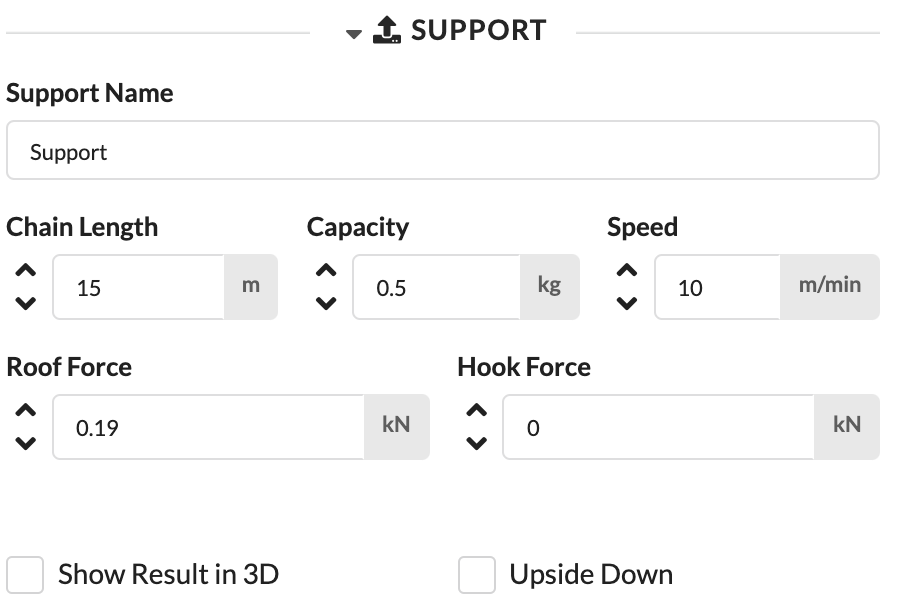
You see this section when you have selected a motor symbol or a symbol with a support point.
For simple symbols, the Name and the Support Name of the object are the same. However, if you have symbols that contain multiple support points, you can give each one a separate name here.
Here you will find information about chain length, load capacity, and speed. These values are important for the Paperwork and the structural calculation and can be changed here.
After a calculation has been performed, the load at the motor (Hook Force – without motor self-weight) and at the attachment point (Roof Force – including motor self-weight) is displayed here.
Here you can show or hide the calculation results at the motor.
If the motor is hung upside down, check this box.
| Panel/Field | Detailed Description |
|---|---|
| Auto-Assign Parts | Automatically assembles the required rope lengths from available rope parts. This allows a matching bridle to be built faster from available material. |
| Parts Excess Length | Defines how much an assembled bridle may deviate from the ideal point if no exactly matching combination is available. This allows the real execution to be represented more accurately. |
| Total Force in Z Direction | Shows the total vertical force at the support. This value is important for evaluating the load situation. |
| Support Name | Sets the name of the support. This helps with unique naming in the plan, in the Paperwork, and in the calculation. |
| Chain Length | Defines the chain length of the support. This information is equally relevant for setup and documentation. |
| Capacity | Sets the load capacity of the support. This makes it easier to check whether the selected support matches the load. |
| Roof Force | Shows the force at the attachment point or roof. This value is displayed after a calculation for verification. |
| Hook Force | Shows the force at the hook or motor. This information also serves the technical evaluation of the support. |
| Use Default Upper Point in Presets | Controls that when placing or using the support, the upper connection point defined in the presets continues to be used instead of being overridden by a preset. This is especially important for chain hoists and dynamically moving systems when only the lower point should be changed by presets. |
| Force Drop Connection | When this option is enabled, this point is treated as a drop. If it is not connected to a structure above, an error message appears; however, the calculation can still be performed. |
| Show Results in 3D | Shows or hides the calculation results in the 3D view. This allows you to check the results directly in the model. |
| Upside Down | Determines at which position the self-weight of the support equipment is applied in the calculation. If Upside Down is enabled, the weight is applied at the upper node; otherwise at the lower node. This setting only affects the calculation and does not change the 3D symbol. |
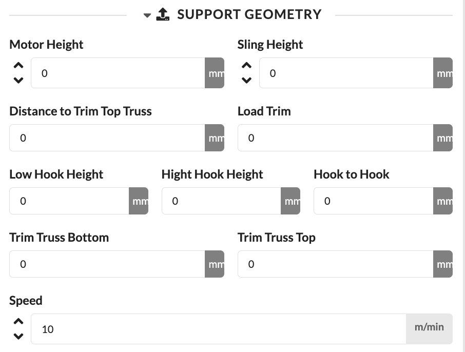
The Support Geometry panel describes dimensions and heights that are important for the setup and calculation of the support.
| Panel/Field | Detailed Description |
|---|---|
| Motor Height | Defines the height of the motor. This allows the real installation situation of the support to be represented more accurately. |
| Sling Height | Defines the height of the sling used. This value is important when the motor, bridle, or sling needs to be considered in terms of height. |
| Distance to Upper Trim Truss | Shows or defines the distance to the upper trim truss. This allows the geometry of the entire support to be precisely traced. |
| Load Trim | Defines the trim height of the load. This value is central for planning, setup, and calculation. |
| Lower Hook Height | Defines the height of the lower hook. |
| Upper Hook Height | Defines the height of the upper hook. |
| Hook Distance | Defines the distance between the upper and lower hook. This makes it easier to verify the actual geometry. |
| Bottom of Trim Truss | Defines the bottom edge of the trim truss. |
| Top of Trim Truss | Defines the top edge of the trim truss. |
| Speed | Sets the hoisting speed. This information can be relevant for technical requirements, workflow, and documentation. |
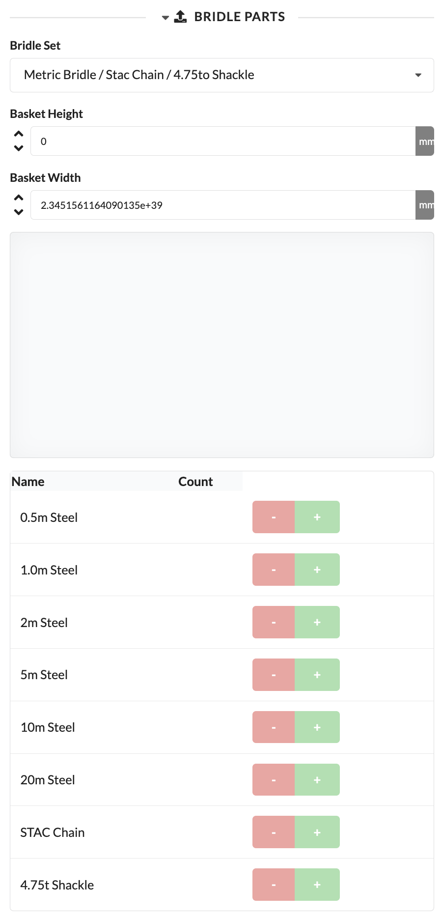
With Bridle Parts, you assemble matching bridle components for the selected support.
| Panel/Field | Detailed Description |
|---|---|
| Bridle Set | Selects the bridle set or parts combination used. This allows the appropriate rigging setup to be quickly adopted. |
| Basket Height | Defines the height of the basket in the bridle. This value affects the geometry of the sling. |
| Basket Width | Defines the width of the basket in the bridle. This allows the bridle to be adapted to the real situation. |
| Name | Shows the available bridle components in the list. The list helps you assemble the required individual parts directly. |
| Count | Increases or decreases the quantity of the respective component. This ensures the bridle is fully and traceably documented. |
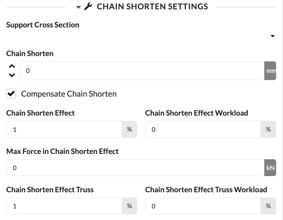
In Chain Shorten Settings, you can check the effect of a chain shortening on the support and structure.
| Panel/Field | Detailed Description |
|---|---|
| Support Cross-Section | Selects the cross-section or type of the support used for the shortening setting. This ensures the calculation is related to the correct geometry. |
| Chain Shortening | Defines by how many millimeters the chain is shortened. This allows you to simulate real adjustments to the chain. |
| Compensate Chain Shortening | Activates the automatic consideration of this support in leveling despite chain shortening. If the option is disabled, this support does not participate in automatic leveling. |
| Chain Shortening Effect | Shows or defines the impact of the shortening in percent. This makes visible how strongly the change takes effect overall. |
| Working Load from Chain Shortening | Shows the impact of the shortening on the working load in percent. This is important for technical evaluation. |
| Maximum Force from Chain Shortening | Shows the maximum force resulting from the shortening effect. This allows you to identify limit ranges faster. |
| Chain Shortening Effect on Truss | Shows or defines the impact on the truss in percent. |
| Truss Utilization from Chain Shortening | Shows the impact on truss utilization in percent. This supports the static assessment of the overall system. |
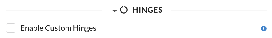
Depending on the object type, additional panels for joints, roof connection, special loads, and structural evaluations appear.
| Panel/Field | Detailed Description |
|---|---|
| Enable Custom Hinges | Enables custom joint conditions for the object. This is relevant when the real load-bearing behavior deviates from the default assumption. |
| Panel/Field | Detailed Description |
|---|---|
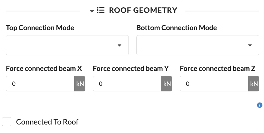
| Upper Connection Mode | Defines how the object is statically and geometrically connected at its upper connection. This is used especially for chain hoists to correctly describe the real attachment situation at the parent structure and to correctly apply it in the calculation. |
| Lower Connection Mode | Defines how the object is statically and geometrically connected at its lower connection. Together with the upper connection mode, this allows the actual connection situation of a chain hoist to be fully described. |
| Connection Force X, Y, Z | Show or define the connection forces in the X, Y, and Z directions at the object's connection. The forces are given in the coordinate system of the structure connected above and help with the technical assessment of which forces are introduced into the supporting structure. |
| Connected to Roof | Manually marks an object or hanging point as connected to the roof. This information is not automatically derived from geometry or supports and serves exclusively for structured documentation and evaluation, for example for filtering or sorting in tables and lists. |
These settings are only relevant for internal connections. For the upper and lower connection modes, options such as Single Tube, Bar, Sling Top, and Sling Top and Bottom are available depending on the situation.
| Panel/Field | Detailed Description |
|---|---|
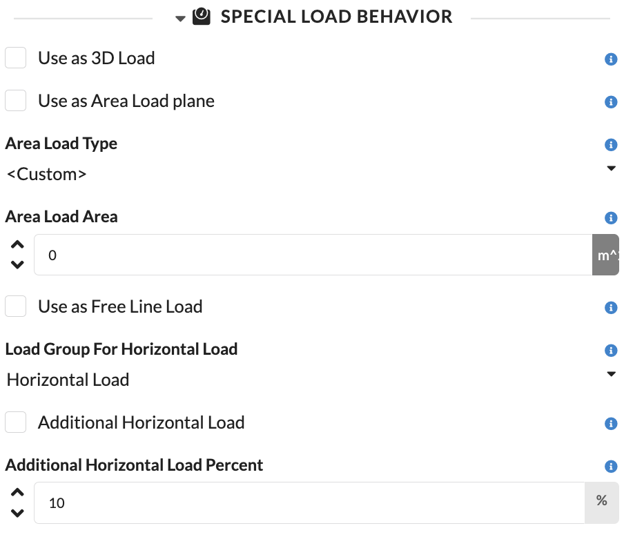
| Use as 3D Load | Uses the 3D body of the object as a load volume for the calculation. If the option is enabled, the object is statically considered as a spatial volume body with uniform density distribution. This is particularly useful when the spatial effect of a real body should be considered in the structural assessment. |
| Use as Area Load | Uses the object in the calculation as an area load. The weight is then not applied as a point or volume load but as a load distributed over an area. A prerequisite is that a polygon exists in the object. |
| Area Load Type | Defines how the area load is determined for the object. By default, the actual weight of the object is distributed over the calculated area; alternatively, a flat-rate load assumption can be used, for example for typical setups such as scaffolding or platforms. |
| Area Load Area | Shows the automatically calculated area used for the area load of this object. The value is for inspection only and cannot be manually edited. |
| Use as Free Line Load | Uses the object as a free line load in the calculation. This allows the line load to be freely positioned in space; intersecting or touching structural elements are automatically used as supports for this load. |
| Load Group for Horizontal Load | Defines which load group the horizontal loads of this object are assigned to. This determines how these loads are categorized in the calculation and treated with the appropriate safety and combination factors. |
| Additional Horizontal Load | Activates an additional horizontal load for the object or the associated structure. This additional horizontal load is based on the applied weight as well as further loads of the structure and is introduced as an additional lateral load component into the calculation. |
| Additional Horizontal Load Percent | Defines the percentage at which the additional horizontal load is applied for this object. This derives an object-specific horizontal equivalent load from the applied vertical loads. |
| Panel/Field | Detailed Description |
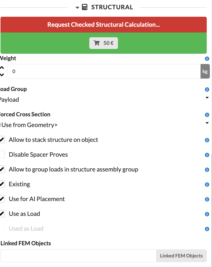
|---|---|
| Request Verified Structural Calculation | With this function, a verified structural calculation can be requested. This is relevant when, in addition to the internal calculation, a formal stability verification is required. In this case, the review is carried out by the internal engineering office of Production Assist. More information can be found on the Static Office page. |
| Weight | Sets the weight of the object. This weight directly enters the load calculation. |
| Load Group | Assigns the object to a load group. This ensures that safety and combination assumptions are correctly applied. |
| Override Cross-Section | Manually overrides the cross-section used for the calculation. This is particularly helpful when different variants need to be quickly checked without changing the symbol or geometry of the object itself. For objects with multiple different structural elements, this function is only of limited use, as all cross-sections of the object are overridden together. |
| Objects Can Be Supported | Defines whether other structural elements can be placed on this object. If the option is enabled, the object can be used as a receiving or load-bearing element in the model logic, allowing Production Assist to create truss cross connections between this and other suitable objects. |
| Disable Spacer Verification | Disables the structural verification calculations for truss spacers for this object. Normally, all short trusses and spacers are considered, which reduces the calculated load capacity. If the truss section has bracings, this option should be enabled so that the full load capacity can be calculated. |
| Object Can Receive Loads | Defines whether loads can be connected to this object and taken over for the calculation. This is particularly helpful for specifically controlling automatic load assignment and excluding certain objects from load reception. |
| Group Loads in Structural Assembly Group | Groups the loads within the structural assembly group. This allows the calculation to be organized more structurally. |
| Exists | Defines whether an object exists in the model and is therefore included in display and calculation at all. If the option is disabled, the object is completely excluded from the active model. This is especially helpful in combination with presets. |
| Use for AI Placement | Defines whether this structure is considered as a possible position during automatic placement of hanging points by the AI. This allows unsuitable areas such as pipes or structurally unsuitable structures to be specifically excluded. |
| Use as Load | Defines whether the weight of an object is considered as a load in the calculation. If the option is disabled, the object remains in the model for other functions, but its weight is not applied. |
| Used as Load in Calculation | Shows whether the object is currently considered as a load in the calculation. This field is read-only, is automatically set, and serves exclusively for information. |
| Linked FEM Objects | Shows linked FEM objects. This allows you to see which additional calculation elements are related to this object. |
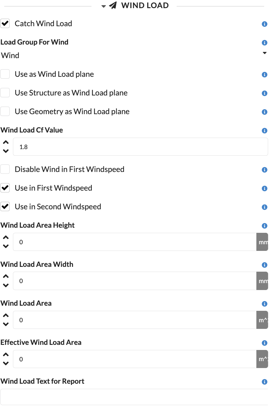
| Panel/Field | Detailed Description |
|---|---|
| Capture Wind Load | Activates the consideration of the object in the wind load calculation. This makes the object treated as wind-relevant in the first place. |
| Load Group for Wind | Defines which load group the wind loads generated by this object are assigned to. This ensures that the appropriate safety and combination factors are applied for wind loads. |
| Use as Wind Load Surface | Defines the object as a wind load surface on which wind pressure is applied across the area. This option is particularly suitable for banners, walls, or other closed surfaces with 2D polygon geometry. |
| Use Structure as Wind Load Surface | Determines the wind attack surface from the underlying structural geometry. This is especially useful for trusses, lattice structures, and other load-bearing elements, as width, height, and where applicable the latticing are taken into account. |
| Use Geometry as Wind Load Surface | Uses the 3D geometry of the object as the basis for the wind load calculation. The 3D body is projected onto a wind load plane depending on the wind direction, allowing the effective area to be determined based on the flow direction. |
| Wind Load CF Value | Sets the aerodynamic force coefficient used to convert the determined wind load surface into an effective wind force. The value accounts for the entire aerodynamic effect from pressure and suction sides and must be determined manually depending on the geometry. |
| Disable at First Wind Speed | Disables the wind load in the first wind load case. |
| Use at First Wind Speed | Defines whether the wind load of this object is considered in the load case of the first wind speed. This allows different setup states, such as with still-mounted attachments, to be specifically represented. |
| Use at Second Wind Speed | Defines whether the wind load of this object is considered in the load case of the second wind speed. This is helpful for simulating changed states at higher wind speeds, for example when banners are removed later. |
| Wind Load Surface Height | Shows the height of the effective wind load surface. This value is automatically calculated and serves for verification. |
| Wind Load Surface Width | Shows the width of the wind load reference surface. Together with the height, this allows you to understand on which geometric basis the wind pressure distribution in the verification was determined. |
| Wind Load Area | Shows the total area applied for the wind load calculation of the object. The value is automatically calculated and primarily serves for verifying the actual wind attack surface applied. |
| Effective Wind Load Area | Shows the effectively applied wind load area after internal reductions or derivations. |
| Wind Load Text for Report | Stores a text block for the structural report. This allows object-specific notes to be directly included in the report. |
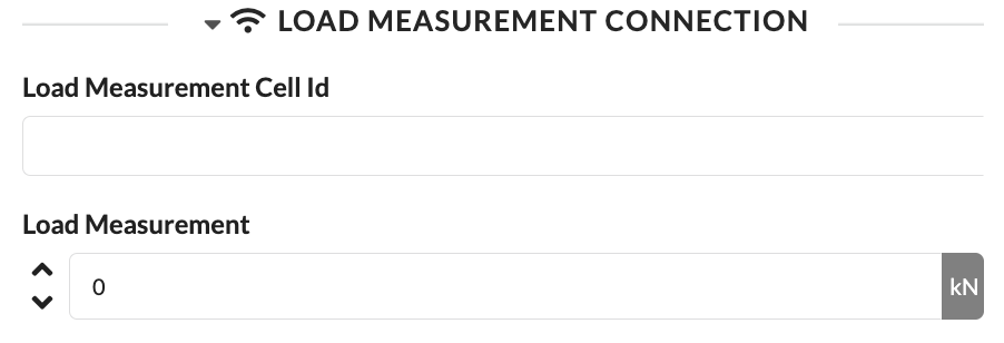
| Panel/Field | Detailed Description |
|---|---|
| Load Cell Identifier | Stores the identifier of the linked load cell. This allows the object to be connected to the matching real measurement point. |
| Load Measurement | Shows or records the measurement value of the load measurement. This allows target and actual values to be compared more easily. |
Here you can store notes for objects.
| Panel/Field | Detailed Description |
|---|---|
| Notes Field | Here you store local notes directly on the object. This is suitable for internal information that should be maintained within the project. |
| Object-Related Information | The screenshot shows that notes can be maintained directly in the object properties. This keeps notes right where they are needed. |
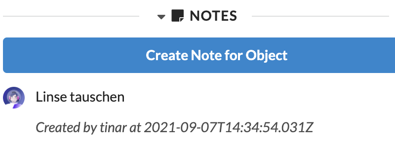
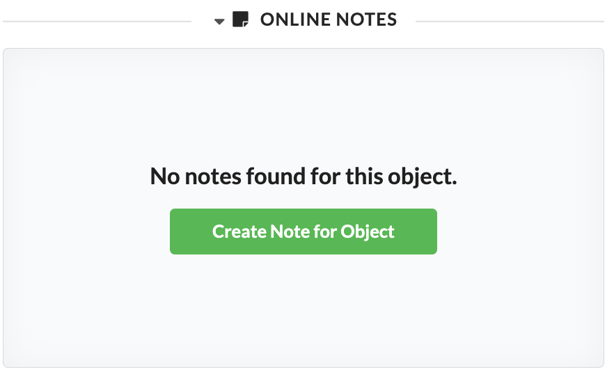
In addition to local notes, there is the Online Notes panel for collaboratively maintained object notes.
| Panel/Field | Detailed Description |
|---|---|
| Create Note for Object | Creates a new online note for the selected object. These notes are particularly suitable for collaboratively maintained information that should not only be stored locally in the document. |
If no online note exists yet, a message appears indicating that no notes are available for this object yet.
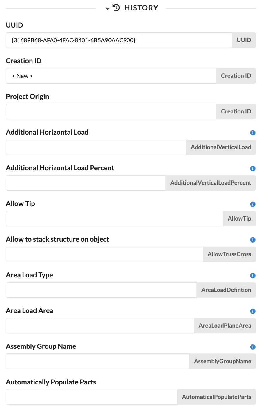
In the History panel, you can see from which saved change state an object originates. You can use this to trace which changes were last documented on this object. This is comparable to change tracking: For daily planning, this panel is usually not important, but it is very helpful for tracing changes.
| Panel/Field | Detailed Description |
|---|---|
| UUID | Shows the unique identifier of the last documented change state. This field is primarily relevant for technical tracking and helps to uniquely assign changes. |
| Creation ID | Shows the identifier under which the object was originally created. This allows you to trace the origin of this object. |
| Project Origin | Shows from which project or data origin the saved state was adopted. This is helpful when content was copied or synchronized from other projects. |
| Additional Fields in Panel | Below, depending on the object, additional saved properties appear, for example Additional Horizontal Load, Allow Tip?, or Assembly Group Name. These values help you better understand previous states of an object. |
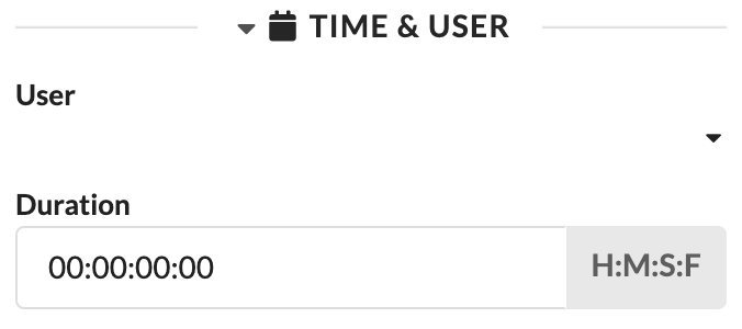
Each object or each Assembly Group can be assigned a User as well as an estimated working time (Duration). You can already use these details in the Worksheets to distribute work packages to different technicians and evaluate the expected time expenditure.
To assign a User to an object, the project must be online and the Users must have been previously created in the Navigation.
| Panel/Field | Detailed Description |
|---|---|
| User | Assigns a responsible person to the object. This makes it directly visible who is managing this object or work package. |
| Duration | Stores the planned working time for setup, handling, or processing. This information is helpful for estimates, deployment planning, and later evaluations. |
When editing a template for labels, the Print Label tab appears. Which properties can be found there and how you can create and edit labels is described in the tutorial Create and print labels for your fixtures.
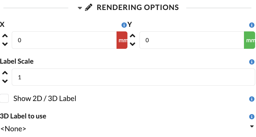
Under Rendering Options, you control the position and display of labels directly on the object.
| Panel/Field | Detailed Description |
|---|---|
| X | Determines the horizontal label offset. This allows you to place the label neatly next to the object. |
| Y | Determines the vertical label offset. This allows you to fine-tune the label position in the plan. |
| Label Scale | Scales the size of the label. This is helpful when labels need to be displayed larger or smaller depending on the scale. |
| Show 2D/3D Label | Shows or hides the label in 2D and 3D. This controls in which views the label is visible. |
| 3D Label | Selects the 3D label to display. This lets you define which label variant is used in the model. |
In the Edit Mode tab, you control object-specific editing modes, provided the selected object type offers such special functions. Which fields are visible here depends entirely on the object type.
At the bottom of the object properties, you will find the modifier options. They define how changes are applied to selected objects.
The concept is similar to the Matricks concept.
| Panel/Field | Detailed Description |
|---|---|
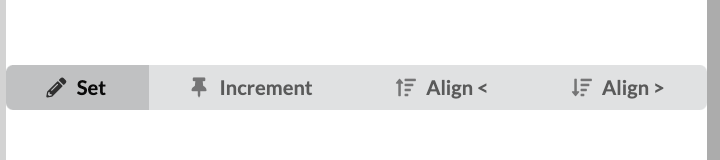
| Set | The selected property is set directly to the same value for all marked objects. This option is useful when all selected objects should receive exactly the same setting. |
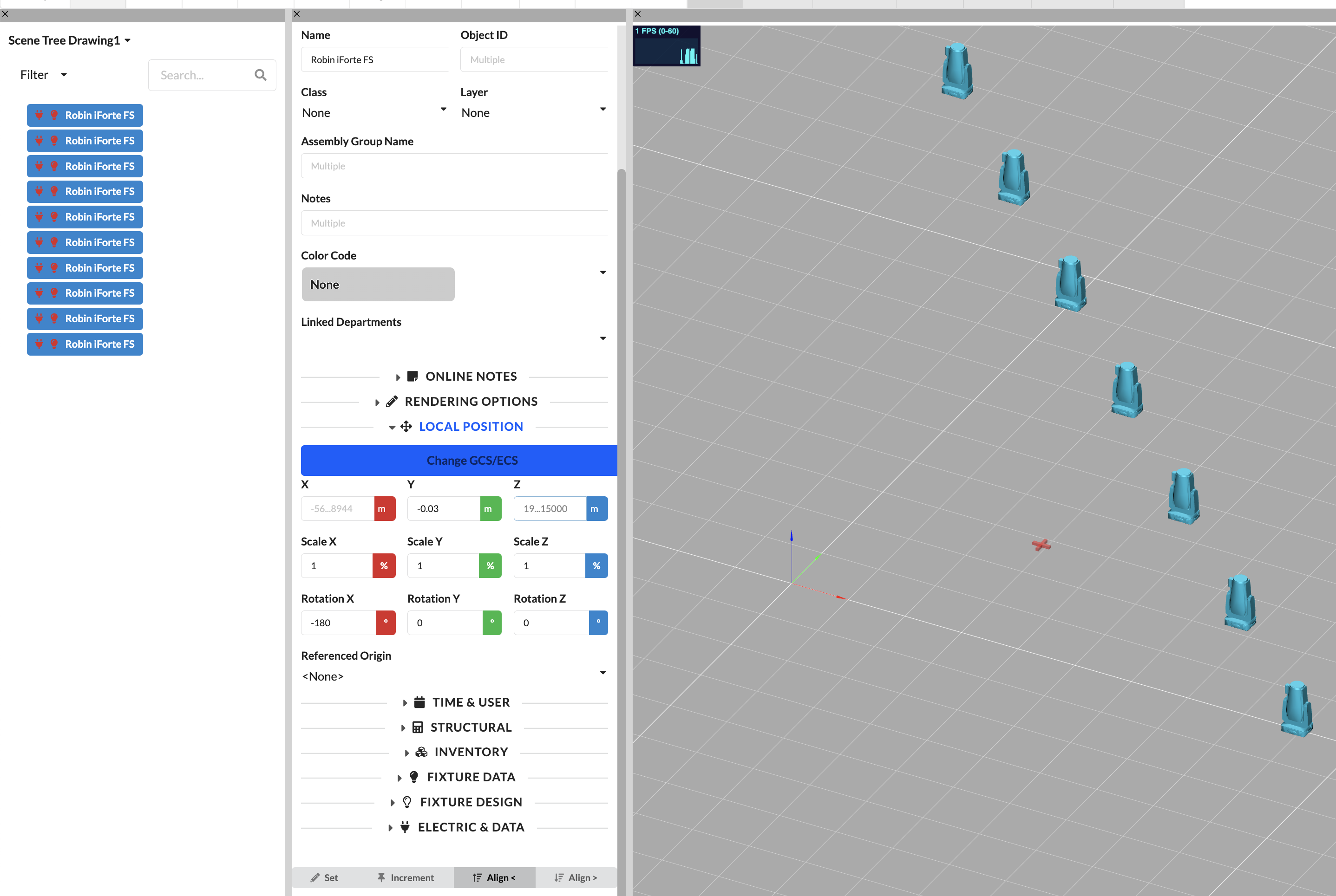
| Increment | The selected property is increased or decreased by the entered value for all marked objects. This is particularly suitable for uniform offsets or staggering. |
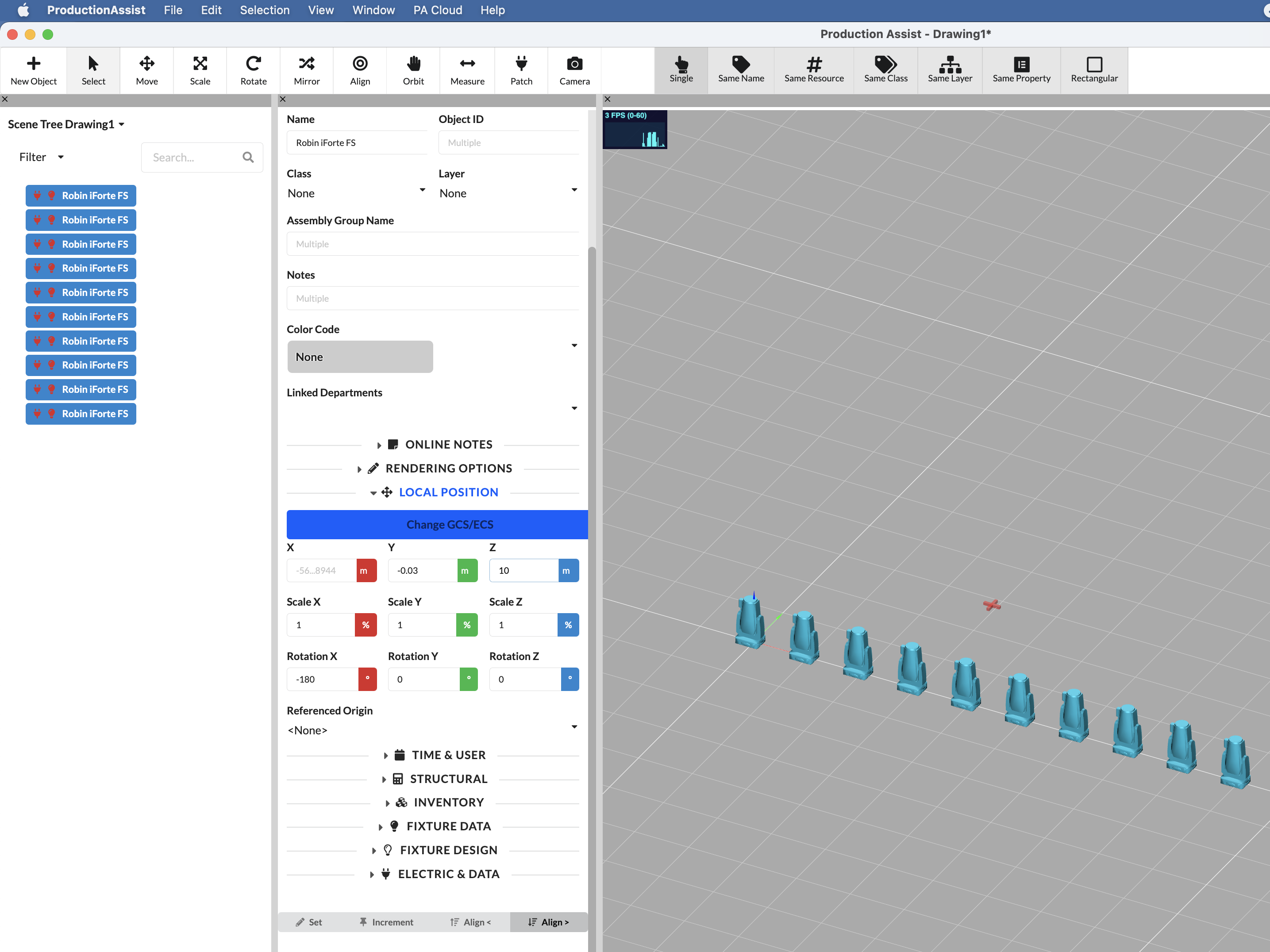
| Align < | The selected property is distributed across the selection, starting from the first selected object. This allows you to arrange values step by step from a starting value. |
| Align > | The selected property is distributed across the selection, starting from the entered target value in the opposite direction. This allows rows or distributions to be built in reverse. |
| Input: 5m | All objects are moved up by 5m |
|---|---|
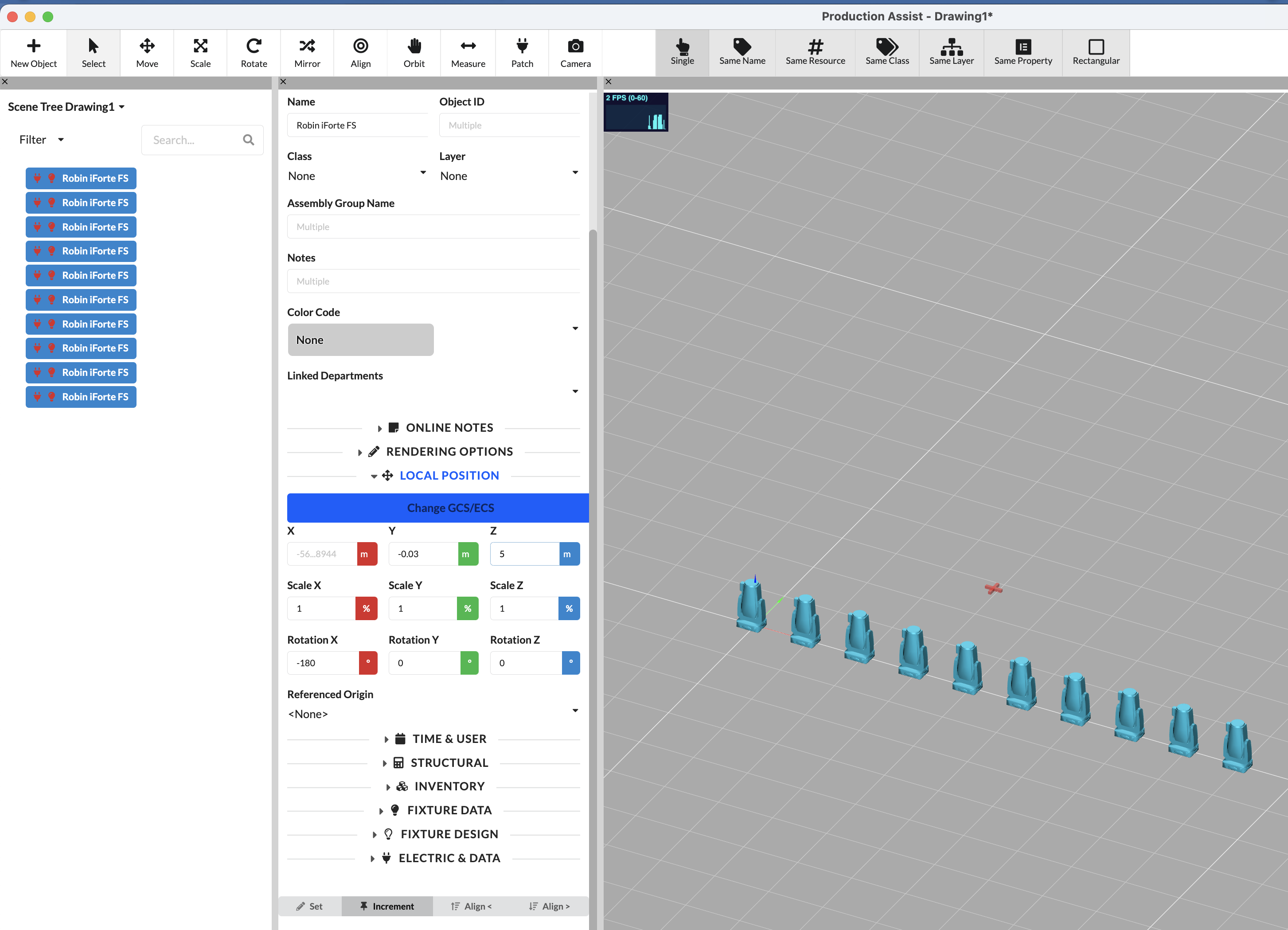 |  |
| Image Part | Detailed Description |
|---|---|
| Left Image | Shows the initial situation before applying Increment. The objects are still at their original height. |
| Right Image | Shows the result after entering 5 m. All selected objects were uniformly moved up by 5 m. |
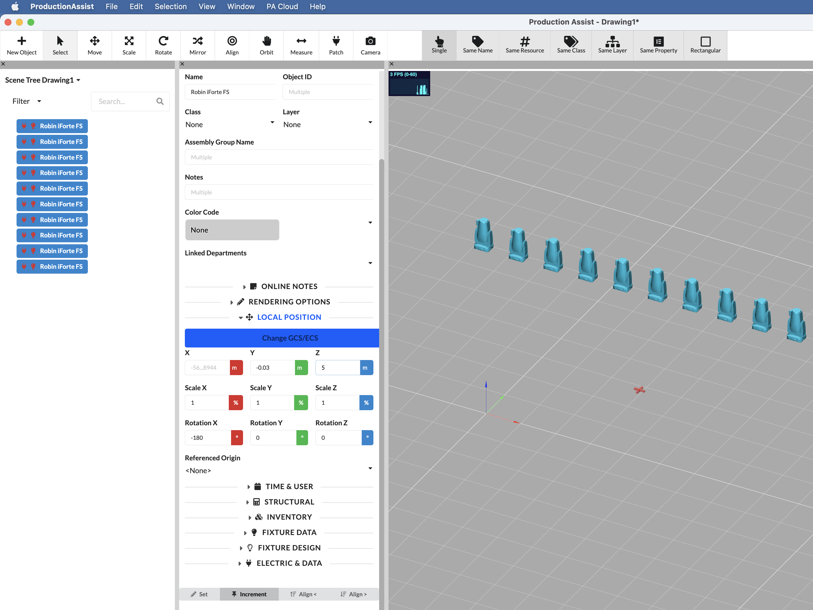
| Input: 10m | All objects are arranged between 0m and 5m |
|---|---|
 |  |
| Image Part | Detailed Description |
|---|---|
| Left Image | Shows the initial situation before distributing with Align <. |
| Right Image | Shows the result of the distribution. The selected objects were arranged step by step between the calculated values. |
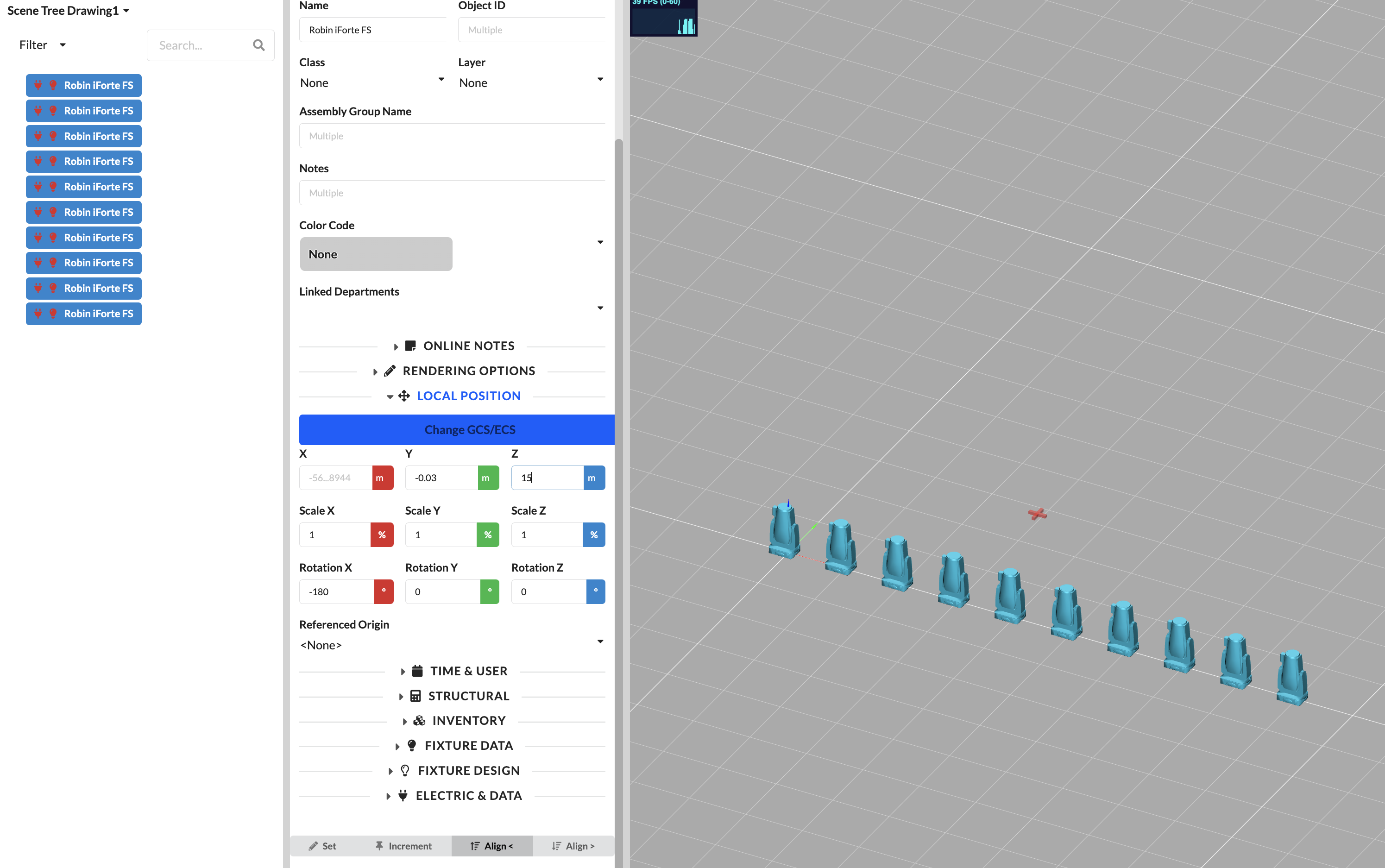
| Input: 10m | All objects are arranged between 0m and 5m |
|---|---|
 | 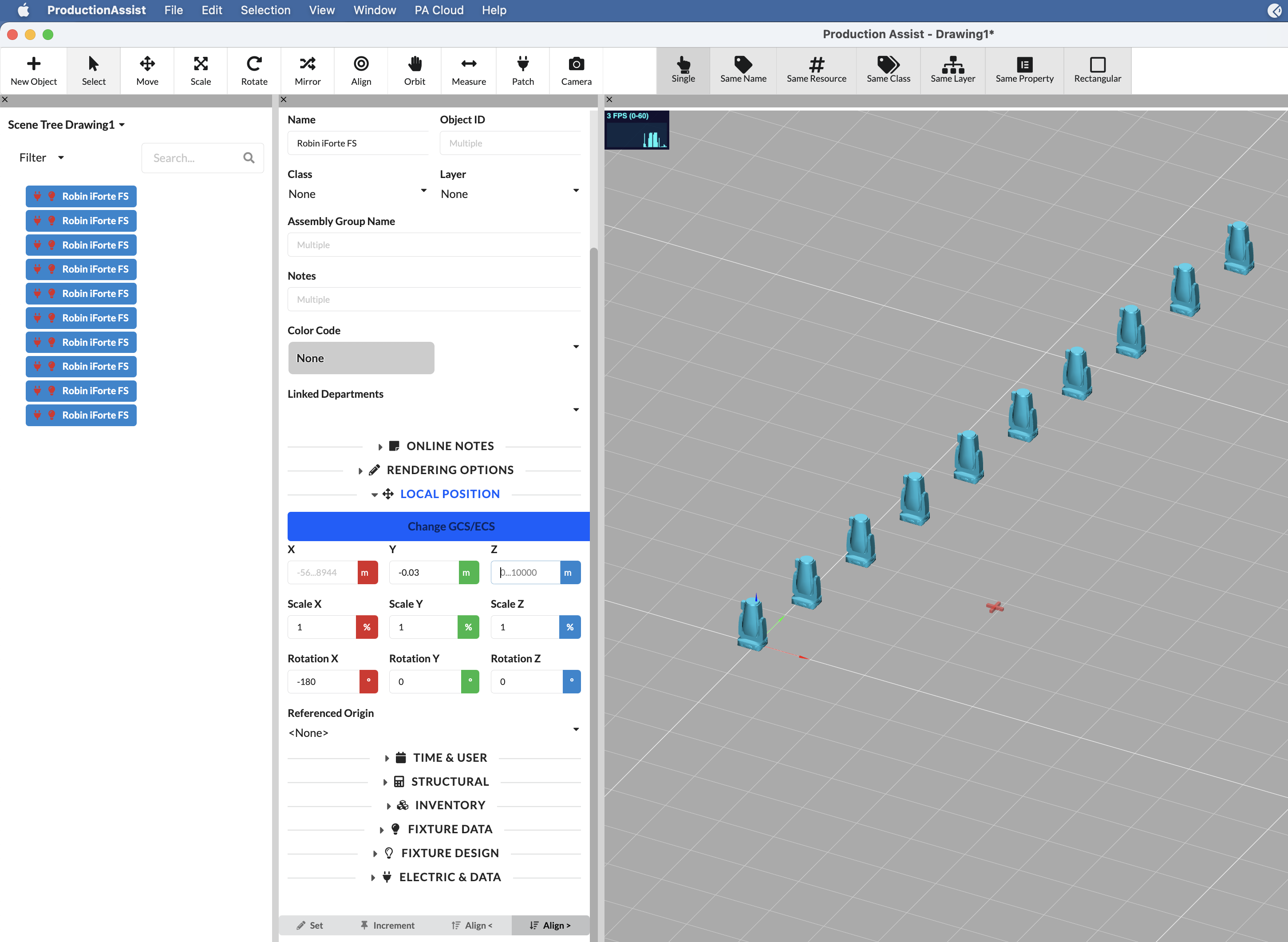 |
| Image Part | Detailed Description |
|---|---|
| Left Image | Shows the initial situation before distributing with Align >. |
| Right Image | Shows the result of the distribution in reverse direction. This shows how values can be mirrored or staggered in reverse across the selection. |
| Name | Description |
|---|---|
| Name | Sets the name of the object that is displayed in lists, worksheets, and reports. This name is often used to group objects, so it should be consistent for all similar objects. |
| Object ID | Sets the unique identifier of the object used for patching and tracking. Can be used to uniquely identify and specifically find objects. |
| Assembly Group Name | The name of the assembly group to which this object belongs. It is used to organize objects in logical groups. When the assembly group name is changed, it also changes in the parent object of the selected object. This relationship is shown in the Scene Tree. |
| Position | The position designation of the object in the scene. It is used to mark the location of the object in the production. This value is freely selectable and independent of the Scene Tree. |
| Notes | Contains free-text notes for the object, e.g., hints for planning, setup, or handover. These notes can be documented for the team and Paperwork. They are not synchronized via the online notes system but via the normal commit system. |
| Color Code | A color code for visually categorizing the object in the scene. Can be used to visually categorize objects and distinguish them in the Paperwork. There are some standard colors; custom colors can be created in the Navigation palette. |
| Department | Sets the department assigned to the object and supports team-based organization in the Paperwork. Can be used to assign responsibilities and evaluate objects in a structured manner. There are some standard departments; custom departments can be created in the Navigation palette. |
| Class | The class category of the object. Through class visibility, the display and filtering of objects can be controlled. Can be used to assign responsibilities and evaluate objects in a structured manner. |
| Layer | The layer to which this object belongs. Layers allow you to control visibility and organization. Can be used to assign responsibilities and evaluate objects in a structured manner. |
| Hang in Center | When this option is enabled, the object is aligned to the center line of the truss. Otherwise, the object is aligned to the corners of the structural element. Can be used to center objects on the truss and maintain symmetry. |
| X | The X position offset of the object in the scene. Can be used to precisely set the spatial position and orientation of the object. |
| Y | The Y position offset of the object in the scene. Can be used to precisely set the spatial position and orientation of the object. |
| Z | The Z position offset (height) of the object in the scene. Can be used to precisely set the spatial position and orientation of the object. |
| Scale X | The scaling factor of the object along the X axis. Can be used to precisely set the spatial position and orientation of the object. |
| Scale Y | The scaling factor of the object along the Y axis. Can be used to precisely set the spatial position and orientation of the object. |
| Scale Z | The scaling factor of the object along the Z axis. Can be used to precisely set the spatial position and orientation of the object. |
| Rotation X | The rotation of the object around the X axis. Can be used to precisely set the spatial position and orientation of the object. |
| Rotation Y | The rotation of the object around the Y axis. Can be used to precisely set the spatial position and orientation of the object. |
| Rotation Z | The rotation of the object around the Z axis. Can be used to precisely set the spatial position and orientation of the object. |
| Origin Reference | Defines which reference point is used as the origin for the position and rotation of this object. Can be used to precisely set the spatial position and orientation of the object. |
| PosiStageNet Send Value | Activates the output of position data via PosiStageNet. This option is only relevant when Production Assist is working as a sender. When the PSN workflow is used, the PSN Tracker ID is automatically created; the PSN server must additionally be activated in the footer. More info is available here. |
| PosiStageNet ID | The numerical ID of the PSN tracker that controls the position of this object. This allows live tracking data to be correctly assigned to the object. In server mode, the ID is automatically generated and cannot be manually changed. In client mode, the PSN ID can be set manually. More info is available here. |
| User | The user responsible for this object in the production. Can be used to assign responsibilities and evaluate objects in a structured manner. |
| Weight | The weight of the object. This value is used in the calculation and indicates the total weight considered for this object. If the value is set to 0 and the object contains structural geometries, the weight from the truss cross-section is used instead of the object weight. |
| Load Group | The load group to which this object belongs. This allows safety factors to be set per group in the structural calculation. |
| Override Cross-Section | With this setting, the cross-section used for the calculation can be manually overridden. By default, Production Assist adopts the cross-section from the geometry or structural definition. This is particularly helpful for quickly checking variants without changing the symbol or geometry. For objects with multiple different structural elements, all cross-sections are overridden together. |
| Capture Wind Load | Activates the consideration of this object in the wind load calculation as a wind surface. This allows individual objects to be specifically excluded from the wind load. An example is a wind load surface on scaffolding where the diagonals should not receive wind load. |
| Load Group for Wind | Defines which load group the wind loads generated by this object are assigned to. This is important because different safety and combination factors apply for wind loads depending on the load type and verification type than for the object itself. An object can belong to one load group while the resulting wind loads must be assigned to another load group with different factors. Typical examples are trusses whose self-weight is treated as a permanent load while the wind load on them is treated as a variable action. |
| Use as Wind Load Surface | Defines this object as a wind load surface on which wind pressure is applied across the area. This is treated according to Eurocode as a wall. Depending on height and width, the wind pressure is distributed accordingly. For the surface to be correctly recognized, a 2D polygon must be present in the object; 3D bodies are not supported. The wind surface is always oriented towards the wind. When the wind runs in the plane of the surface, no wind pressure is applied. The Effective Wind Load Area shows how much of the total wind load area is used. |
| Use Structure as Wind Load Surface | Defines the object as a wind load surface whose wind attack surface is determined from the underlying structural geometry. This option is primarily used for lattice structures, trusses, and other load-bearing elements. A prerequisite is existing structural geometry; from this, Production Assist calculates the effective wind load area from width, height, and for trusses additionally from the latticing. As a result, the wind load is not applied as a full closed surface but according to the effective impacted structural surface. |
| Use Geometry as Wind Load Surface | Uses the 3D geometry of the object as the basis for the wind load calculation. If the option is enabled, the 3D body is projected onto a wind load plane depending on the wind direction, and the effective area is determined from this. This is particularly useful for three-dimensional components such as fixtures, decorative elements, or other compact 3D objects. |
| Wind Load CF Value | Sets the aerodynamic force coefficient (Cf) for the wind load calculation. It describes the entire aerodynamic effect from the pressure and suction sides on the object and directly affects the applied wind force. Typical values are often in a range of approximately 1.2 to 2.0, depending on shape and flow conditions. The value must be set manually; the default value is deliberately chosen conservatively. |
| Disable at First Wind Speed | When this option is enabled, the object is not considered in the load case of the first wind speed. This allows, for example, certain objects to be excluded from the calculation that are only used at higher wind speeds to reinforce the structure. |
| Use at First Wind Speed | Defines whether the wind load of this object is considered in the load case of the first wind speed. If the option is enabled, the wind load of the object is included in this load case; if disabled, it remains unconsidered there. This allows different setup states to be represented for different wind speeds without completely removing the object from the model. |
| Use at Second Wind Speed | Defines whether the wind load of this object is considered in the load case of the second wind speed. This option is typically used to simulate changed states at higher wind speeds, for example when banners or cladding are removed above a certain wind speed. |
| Wind Load Surface Height | The height of the wind load reference surface. This value cannot be changed and is purely informational. It is considered to calculate the ratio between width and height, and thus the distribution of wind pressure. |
| Wind Load Surface Width | Shows the width of the wind load reference surface used for the wind load calculation of the object. The wind load surface width is automatically determined by Production Assist and cannot be manually changed. Together with the associated height of the wind load surface, this allows you to understand on which geometric basis the distribution of wind pressure in the verification was determined. |
| Wind Load Area | Shows the total area applied for the wind load calculation of the object. The value is automatically calculated and displayed for information only. This allows you to understand with which actual wind attack surface an object enters the calculation and whether the applied area corresponds to the expected modeling. |
| Effective Wind Load Area | The effective area after application of any reduction factors for the wind load calculation. This value is automatically calculated and displayed here. |
| Wind Load Text for Report | Markdown text for this wind load area. These notes are printed in the structural report. This allows a text to be specified for each wind force in the report. |
| Use as 3D Load | With this setting, the 3D body of the object is used as a load volume for the calculation. If the option is enabled, the object is statically considered as a spatial volume body with uniform density distribution. Surrounding supporting structural elements are used as supports for this load volume. A prerequisite is an actual 3D geometry in the object. |
| Use as Area Load | With this setting, the object is used as an area load in the calculation. The weight of the object is then not applied as a point or volume load but as a load distributed over an area. A prerequisite is a polygon in the object that serves as the basis for the area load calculation. |
| Area Load Type | Defines how the area load is determined for the object. By default, the actual object weight is distributed over the calculated area. Alternatively, a flat-rate load assumption can be used, for example for typical setups such as scaffolding or platforms. |
| Area Load Area | This display shows the automatically calculated area used for the area load of this object. The value is for inspection only and cannot be manually edited. |
| Use as Free Line Load | With this setting, the object is used as a free line load in the calculation. The line load can thereby be freely positioned in space without all vertex points having to lie directly on a structural element. Intersecting or touching structural elements are automatically used as supports. |
| Load Group for Horizontal Load | Defines which load group the horizontal loads of this object are assigned to. This determines how these loads are categorized within the calculation and treated with the appropriate safety and combination factors. |
| Additional Horizontal Load | Activates an additional horizontal load for the object or the associated structure. In addition to the normal load application, an additional lateral load component is considered, which is based on the applied weight and further loads of the structure. |
| Additional Horizontal Load Percent | Defines the percentage at which the additional horizontal load is applied for this object. The percentage value controls the object-specific horizontal equivalent load in relation to the underlying load. |
| Truss Cross Type | Defines the load-bearing behavior of supported trusses. - Flexible: Allows rotations in all directions. - Compression Only: Transfers only compressive forces. - Tension Only: Transfers only tensile forces. - Rigid: Transfers forces and moments without relative movement. |
| Transmitted Force Design Value | The design force acting on the truss cross. Displayed here only and cannot be edited. The design force includes the safety factors. |
| Transmitted Force Characteristic Value | The characteristic (unfactored) force of the truss cross. Displayed here only and cannot be edited. |
| Objects Can Be Supported | Defines whether other structural elements can be placed on this object. If the option is enabled, the object can be used as a receiving or load-bearing element so that truss cross connections or corresponding support situations can be created between it and other suitable objects. |
| Disable Spacer Verification | Disables the structural verification calculations for truss spacers for this object. Normally, all short trusses and spacers are considered, which reduces the calculated load capacity. If the truss section has bracings, this option should be enabled so that the full load capacity can be calculated. Only affects truss cross-sections, not others. |
| Object Can Receive Loads | Defines whether loads can be connected to this object and taken over for the calculation. If the option is enabled, loads can be connected to this object. If disabled, the object does not receive loads even if loads are geometrically nearby. This setting is particularly helpful for specifically controlling automatic load assignment and defining which structural parts should actually receive loads. |
| Exists | Defines whether an object exists in the model and is therefore included in display and calculation at all. If the option is enabled, the object exists in the model and is considered with its properties. If disabled, the object is completely excluded. It is then neither displayed in the 3D view nor included with any property in the calculation. This is especially helpful in combination with presets. |
| Use for AI Placement | Defines whether a structure is considered as a possible position during automatic placement of hanging points by the AI. If the option is enabled, the structural element can be used by the AI hanging point placer for suitable positions. If disabled, this structure is excluded. This allows unsuitable areas such as pipes or structurally unsuitable structures to be specifically excluded from AI placement. |
| Use as Load | Defines whether the weight of an object is considered as a load in the calculation. If the option is enabled, the object is included with its weight in the calculation model. If disabled, the object remains in the model for other functions, but its weight is not applied as a load. For general showing and hiding of objects in the calculation, it is generally recommended to use the pause button via layers or classes instead. |
| Used as Load in Calculation | Shows whether the object is currently considered as a load in the calculation. The value is read-only and cannot be manually edited. It is automatically set by Production Assist and serves exclusively for information and verification of whether an object actually enters the calculation. |
| Manufacturer | The name of the manufacturer of this object. Can be used to uniquely identify and specifically find objects. |
| Supplier | The name of the supplier from whom this object was sourced. Can be used to uniquely identify and specifically find objects. |
| Purpose | A description of the purpose or function of this object in the production. Can be used to consistently document and evaluate the object configuration in the project. |
| Part Number | Sets the manufacturer part number of the object, e.g., for ordering and inventory management. Can be used to uniquely identify and specifically find objects. |
| Use as Cable Definition | Marks this geometry as a cable inventory item used as a cable element. |
| Allowed Excess Cable Length | Specifies from what cable excess the cable is assembled from shorter cables. With a value of 5 m, an excess of up to 5 m is accepted without needing to supplement shorter segments. |
| Required Document | Links an object with a document. This allows, for example, certificates or inspection reports to be assigned. New documents can be created in the Resource Manager under Documents. |
| CO2 Footprint | The CO2 footprint of this object in grams. Used for sustainability reporting. |
| Costs | The costs for this object. Used for budget tracking and reporting. |
| Linked Case Template | The template used when packing this object into a case. Can be used to consistently represent packing logic and transport planning. |
| Linked Container | The container in which this object is packed. This can be either a truck, a case, or a rack. These can be created in the Navigation. |
| Position in Rack | If the object is placed in a rack, this property indicates the position within the rack. The unit is rack units (HE/U). |
| Case | Defines whether the object has its own case or transport box. Can be used to consistently represent packing logic and transport planning. |
| Has Wheels | Defines whether the object or its case is equipped with casters. Can be used to consistently represent packing logic and transport planning. |
| Allow Tip? | Defines whether the object may be tipped or rotated during packing. Can be used to consistently represent packing logic and transport planning. |
| Position in Container X | The X offset of this object's position within the container. Can be used to consistently represent packing logic and transport planning. This value is automatically calculated when the object is placed in a container. |
| Position in Container Y | The Y offset of this object's position within the container. Can be used to consistently represent packing logic and transport planning. This value is automatically calculated when the object is placed in a container. |
| Position in Container Z | The Z offset of this object's position within the container. Can be used to consistently represent packing logic and transport planning. This value is automatically calculated when the object is placed in a container. |
| Case Size X | The width (X dimension) of the transport case. Can be used to consistently represent packing logic and transport planning. |
| Case Size Y | The depth (Y dimension) of the transport case. Can be used to consistently represent packing logic and transport planning. |
| Case Size Z | The height (Z dimension) of the transport case. Can be used to consistently represent packing logic and transport planning. |
| Rotation in Container X | The rotation of the object around the X axis within the container. Can be used to consistently represent packing logic and transport planning. |
| Rotation in Container Y | The rotation of the object around the Y axis within the container. Can be used to consistently represent packing logic and transport planning. |
| Rotation in Container Z | The rotation of the object around the Z axis within the container. Can be used to consistently represent packing logic and transport planning. |
| Count HE in Rack | The height of this object measured in rack units (HE/U). Can be used to consistently represent packing logic and transport planning. |
| X | The horizontal offset of the label relative to the object's origin. This allows the label to be correctly positioned in the 2D view. |
| Y | The vertical offset of the label relative to the object's origin. This allows the label to be correctly positioned in the 2D view. |
| Label Scale | The scaling factor applied to the label displayed on this object. This allows the label to be correctly scaled in the 2D view. |
| Show 3D Label | Controls whether the assigned 2D/3D label of this object is visible in the viewport. This allows the label to be displayed in 2D and 3D views. |
| 3D Label | The label used to display information about this object in the 3D view. This allows the label to be displayed in the view. |
| Closed | Defines whether the polygon is closed (last point connected to first point). |
| Fill | Fills the interior of the polygon with the selected fill color. |
| Draw Background | Draws a background behind the polygon shape. Can be used to control the visual representation of the object in 2D/3D. |
| Line Width | The width of the polygon outline. Can be used to control the visual representation of the object in 2D/3D. |
| Line Style | The style of the polygon outline (e.g., solid, dashed, dotted). Can be used to control the visual representation of the object in 2D/3D. |
| Line Color | The color of the polygon outline. Can be used to control the visual representation of the object in 2D/3D. |
| Fill Color | The fill color of the polygon interior. Can be used to control the visual representation of the object in 2D/3D. |
| Background Color | The background color drawn behind the polygon. Can be used to control the visual representation of the object in 2D/3D. |
| Line Transparency | The transparency of the polygon outline. 0 = fully transparent, 1 = fully opaque. Can be used to control the visual representation of the object in 2D/3D. |
| Fill Transparency | The transparency of the polygon fill. 0 = fully transparent, 1 = fully opaque. Can be used to control the visual representation of the object in 2D/3D. |
| Extrusion Height | The height to which the polygon is extruded into a 3D shape. Can be used to control the visual representation of the object in 2D/3D. |
| Texture | The image texture applied to the surface of this polygon. Can be used to control the visual representation of the object in 2D/3D. |
| Horizontal Offset | The horizontal offset of the texture on the polygon surface. Can be used to control the visual representation of the object in 2D/3D. |
| Vertical Offset | The vertical offset of the texture on the polygon surface. Can be used to control the visual representation of the object in 2D/3D. |
| Scale | The scaling factor applied to the texture on the polygon surface. Can be used to control the visual representation of the object in 2D/3D. |
| Rotation | The rotation angle of the texture on the polygon surface. Can be used to control the visual representation of the object in 2D/3D. |
| Constrain Translation X | Allow or lock movement along the X axis. Can be used to limit permitted movement or rotation freedoms. |
| Constrain Translation Y | Allow or lock movement along the Y axis. Can be used to limit permitted movement or rotation freedoms. |
| Constrain Translation Z | Allow or lock movement along the Z axis. Can be used to limit permitted movement or rotation freedoms. |
| Constrain Rotation X | Allow or lock rotation around the X axis. Can be used to limit permitted movement or rotation freedoms. |
| Constrain Rotation Y | Allow or lock rotation around the Y axis. Can be used to limit permitted movement or rotation freedoms. |
| Constrain Rotation Z | Allow or lock rotation around the Z axis. Can be used to limit permitted movement or rotation freedoms. |
| Draw Beam | Marks the geometry as a beam element for structural analysis. Can be used to control structural calculations and verifications on a per-project basis. |
| Linked Mesh | The mesh geometry linked to this object. The mesh defines the 3D shape. Can be used to assign geometry or texture bases for display and analysis. |
| Linked Image | The image or texture linked to this object. Can be used to assign geometry or texture bases for display and analysis. |
| Mark as Fully Connected | Marks all electrical connections of this object as connected, even if the connection was made outside the software. Can be used to correctly document the electrical planning status. |
| Preliminary Mains Connection | The generator to which this consumer is preferably connected. Can be used to correctly document the electrical planning status. |
| Default Power Cable Length | The default cable length used in automatic cable connection planning for this object. Can be used to reliably plan logistics, availability, and cost processes. |
| Count | The number of items of this type in the inventory. Can be used to reliably plan logistics, availability, and cost processes. |
| Length | The length of this object (e.g., cable, beam, pipe). Can be used to reliably plan logistics, availability, and cost processes. |
| Minimum Length | The minimum acceptable length for this object. Can be used to reliably plan logistics, availability, and cost processes. |
| Available From | The date and time from which this object (e.g., generator) is available. Can be used to reliably plan logistics, availability, and cost processes. |
| Available Until | The date and time until which this object (e.g., generator) is available. Can be used to reliably plan logistics, availability, and cost processes. |
| Enable Custom Hinges | Sets custom joint conditions at the connection point of this object. Enables control over which internal forces are transmitted. Can be used to precisely define the force transmission behavior at connections. |
| Hinge Nx | Defines whether the normal force Nx is transmitted through this joint connection. Joints are used in the calculation to specifically influence the force and deformation behavior of connections. This option specifies in detail whether the normal force in the longitudinal direction of the connected element is still transmitted despite the joint definition or not. This option is an expert setting and should only be used when the desired static effect of the connection is precisely known. |
| Hinge Vy | Defines whether the shear force Vy is transmitted through this joint connection. Can be used to precisely define the force transmission behavior at connections. |
| Hinge Vz | Defines whether the shear force Vz is transmitted through this joint connection. Can be used to precisely define the force transmission behavior at connections. |
| Hinge Mt | Defines whether the torsion Mt is transmitted through this joint connection. Can be used to precisely define the force transmission behavior at connections. |
| Hinge Mby | Defines whether the bending moment Mby is transmitted through this joint connection. Can be used to precisely define the force transmission behavior at connections. |
| Hinge Mbz | Defines whether the bending moment Mbz is transmitted through this joint connection. Can be used to precisely define the force transmission behavior at connections. |
| Inventory Type | The type of inventory item (e.g., standard, cable, bridle part). Can be used to reliably plan logistics, availability, and cost processes. |
| Structure Extension X | The X offset applied when extending this structure. This allows structural geometries to be specifically extended for the calculation and minor geometry issues to be resolved. The coordinate system is aligned to the associated magnet. |
| Structure Extension Y | The Y offset applied when extending this structure. This allows structural geometries to be specifically extended for the calculation and minor geometry issues to be resolved. The coordinate system is aligned to the associated magnet. |
| Structure Extension Z | Defines the offset in the Z direction by which the associated structure is extended for the calculation. The value is used to specifically extend structural elements such as trusses by a small amount, compensate for geometric inaccuracies, and better represent special situations such as curved runs or grapples. The coordinate system used refers to the associated magnet. |
| Allow Uplift Forces | Activates nonlinear behavior for the support. If the support in the calculation would need to absorb tensile forces and would thus lift off, it is considered as failed at this point and can no longer transfer forces. This realistically represents that a support loses contact with the ground as soon as no compressive force is present. This setting is particularly important for tipping verifications and for systems where individual supports can be relieved or fully lifted. |
| Upside Down | Determines at which position the self-weight of the support equipment is applied in the calculation. If Upside Down is enabled, the weight is applied at the upper node; otherwise at the lower node. The option is used exclusively for the calculation, has no influence on the 3D display, and does not graphically change the symbol. |
| Rotated Support | When this setting is enabled, the rotation of the object is transferred to the associated FEM support. The support then no longer aligns exclusively with the global coordinate system but follows the orientation of the object. This is particularly important for inclined or rotated planes so that the support is correctly represented according to the real installation situation. |
| Connected to Roof | Manually marks an object or hanging point as connected to the roof. This information is not automatically derived from geometry or supports and has no influence on the calculation, structural model, or load distribution. It serves exclusively for structured documentation and evaluation. |
| Friction Coefficient Between Floor and Support | Defines the friction coefficient between the base of the support and the existing floor surface. The value is used for the verification against sliding and is thus an essential component of the stability verification. The higher the value, the greater the resistance against horizontal displacement. Typical values are between 0 and 1 depending on the material pairing; a common default value is 0.4. Additionally, a suitable friction coefficient according to Eurocode can be selected via the dropdown. |
| Use Default Upper Point in Presets | Controls that when placing or using the support, the upper connection point defined in the presets continues to be used instead of being overridden by a preset. This is especially important for chain hoists and dynamically moving systems when only the lower point should be changed by presets. |