

Use the Production Assist (PA) plug-in to transfer your Vectorworks drawing into a structural model. Draw structures, loads, and suspensions in Vectorworks, then check connections, forces, deformations, and utilization in the Production Assist web palette. Alternatively, you can connect the desktop app to the plug-in and use it as the interface.
Production Assist reads supported objects and synchronizes their properties with Vectorworks. Which values are transferred depends on the object type and the configured field mappings. Use the Properties Map to transfer additional supported fields in both directions.
The web palette contains the Production Assist workspaces and calculation functions. Additional Vectorworks commands are available in the Production Assist menu. The available object types and commands depend on the Vectorworks version, plug-in version, license, and workspace.

To work with the integration, you need:
Start with a small, complete system and check that it transfers correctly before adding more components. The Vectorworks quick start is a good place to begin. The workflow for a complete structure guides you through the subsequent model and result checks.
The installation through the Production Assist desktop app detects existing Vectorworks versions and downloads the matching plug-in. The following steps describe manual installation from the download archive.
For manual installation, the Production Assist desktop app must be installed and have been started at least once. If you use the portable desktop app, you must also point the plug-in to the ProductionAssist-data folder; the steps are described in Configure the plug-in AppData directory.
ProductionAssistWeb folder and the files ProductionAssist.vlb and ProductionAssist.vwr.%APPDATA%\\Nemetschek\\Vectorworks\\<Jahr>\\Plug-ins. Replace <Jahr> with the version number.
The image shows an older package with several version folders. In the downloaded archive, use only the files for your installed Vectorworks version.
ProductionAssist.vwlibrary.~/Library/Application Support/Vectorworks and select the folder for your Vectorworks version.ProductionAssist.vwlibrary into its Plug-ins folder.Remove the quarantine attribute: Apple may mark downloaded files with a quarantine attribute. Open Terminal and enter
xattr -d com.apple.quarantine. Add a space, then drag the downloaded ZIP file into the Terminal window. Check the file path and the space between the command and the path. Then press Enter.


The Finder image shows VW21 as an example. In the downloaded archive, select the folder for the Vectorworks version you actually have installed.
Start Vectorworks and open a new or existing drawing. Select Window → Web Palettes → Production Assist.

When opened, the web palette checks whether a valid sign-in is already available. If the sign-in screen appears, connect to the internet and sign in with your Production Assist account. Alternatively, you can select Sign in with Azure. After signing in successfully, the user interface is displayed.
Without an internet connection, the sign-in screen is not skipped for a new or no longer valid session. If the palette is already open in a valid signed-in session and the connection is lost later, you can continue editing the open drawing. Online resources and online projects require a connection again. For preparation tips, see Working without an internet connection.
In the web palette, switch between the tabular Worksheet and the 3D Planning view. Older interfaces use Worksheet and Edit for these views. The 3D view shows how Production Assist imported the drawing; it is especially useful for checking structures and connection points.
For an overview of the user interface, see User interface.
| Area | Use in Vectorworks |
|---|---|
| Object Properties | Shows properties of the objects selected in Vectorworks. Supported fields, such as fixture weight, can be synchronized in both directions. Edit PA-specific values, such as wind load assumptions, here. |
| Scene Tree (Structure) | Hierarchical object list for finding and selecting objects. A selection in the Scene Tree is applied in Vectorworks. For example, search for the Object ID of a chain hoist. |
| Properties / worksheets | Shows selected columns, such as Object ID, name, assembly group, position, weight, roof force, and connection status. Templates such as Load Overview make checking easier. |
| Navigation | Includes layers, classes, selection groups, load groups, load combinations, and section reactions. Layers and classes correspond to the Vectorworks assignments that were transferred. |
| Resource Manager | Manages symbol definitions, cross-section templates, materials, and mappings. Open it through Window → Resource Manager. |
| Rigging | Contains calculation, calculation scope, connections, system selection, and special operations. |
| Lighting | Includes Power Patch and electrical calculation. These functions have their own workflow; see Electrical planning. |
A multi-selection shows shared properties and lets you change them together. Check the selection before correcting a weight: the value you enter is set for each selected object; it is not the total weight of the selection.
Use Selection Groups to save recurring selections, such as the suspension points of a tent arch. A group total helps with the overview. Distinguish the sum of object weights from the sum of calculated roof forces; they have different meanings for chain hoists and multi-stage suspensions.
You can change the language using the language selector in the bottom bar. It also affects Production Assist calculation messages. For more controls, see User interface, Scene Tree, Navigation, and Worksheets.
If only an empty area remains after closing all docked tabs, click Reset UI. This restores and saves the default arrangement of the web palette. Help appears in both the model view and the worksheet view; see Restore the default arrangement.
First select the objects directly in Vectorworks. Find these commands in the Production Assist menu:
| Axis | Copy in positive or negative direction | Move in positive or negative direction |
|---|---|---|
| X | CX+ - Copy X, CX- - Copy X | MX+ - Move X, MX- - Move X |
| Y | CY+ - Copy Y, CY- - Copy Y | MY+ - Move Y, MY- - Move Y |
| Z | CZ+ - Copy Z, CZ- - Copy Z | MZ+ - Move Z, MZ- - Move Z |
During plug-in setup, you can have the missing commands added to the Production Assist menu group. If you do not want to add the menu group, use the workspace editor to place the commands under Production Assist Native Transform.
The commands use the relevant X, Y, or Z value from Paste Offset. Copy creates copies next to the originals in the same container, then selects the copies. Move moves the selected objects. If at least one selected object is locked, the entire move is canceled. If nothing is selected, nothing changes. Use Vectorworks Undo to undo an action.
Use the Properties Map to link fields of a Vectorworks object type with matching Production Assist properties. For example, use it to read or write custom fields. The existing default mappings apply to CAD block attributes; do not assume that Vectorworks object fields are already mapped.
Values for the same mapped field are transferred in both directions. This applies only to fields with a matching mapping and supported object types; the Properties Map does not synchronize all drawing changes indiscriminately. Other fields, such as Factor and Use Unit, are described in Properties Map.
The following images show the current mapping table and the Add Mapping... dialog:
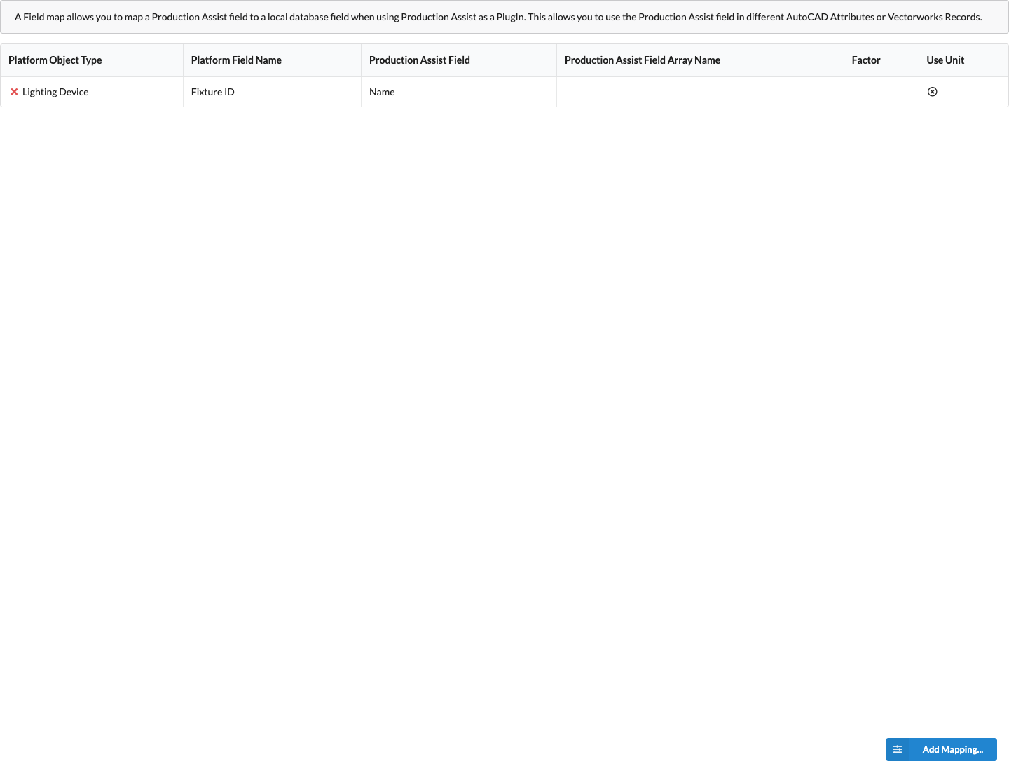
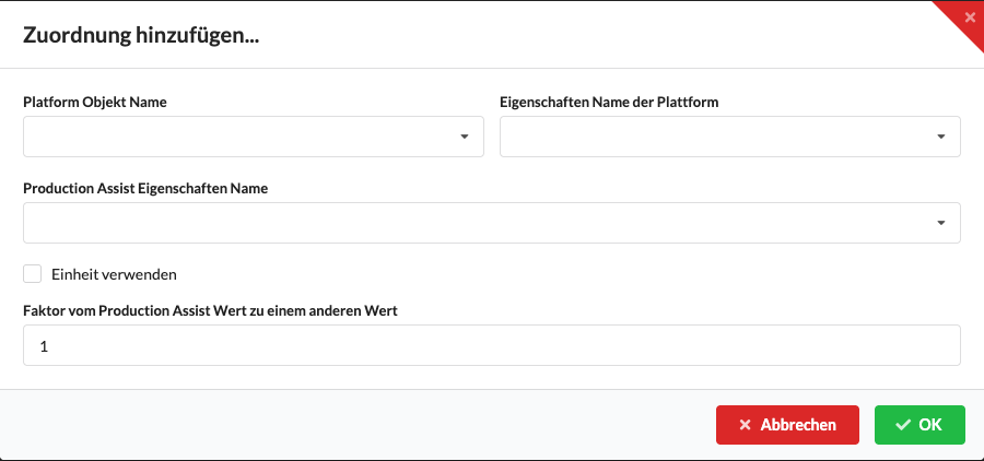
Platform Object Name, Platform Property Name, and Production Assist Property Name are required. You can select a platform field from the list or enter the field name yourself.
| Setting | Effect |
|---|---|
| Use Unit enabled | Uses the unit of the Production Assist value and disables factor entry. |
| Use Unit disabled | Allows conversion using Factor from Production Assist value to another value. The default factor is 1. |
| OK | Adds the completed mapping. |
| Cancel | Closes the dialog without adding a mapping. |
To remove an existing mapping, use the delete icon in its table row. Deletion takes effect immediately. Then check a relevant object to make sure the remaining mappings transfer the required values.

When a drawing opens, the Production Assist import dialog appears if Ask at each start is selected. Always Use activates the integration without this prompt; Manually Enable requires manual activation. Configure this under Vectorworks loading behavior.
The import filter determines which objects PA receives at all. An excluded layer cannot later be restored simply by changing the calculation scope. Read the drawing again with the changed filter. The Production Assist → Update References/Read Vectorworks Drawing again... command updates the imported data; Read and Calculate... reads the drawing again and then starts the calculation.
Use Production Assist without Geometry (faster) skips importing the visible object geometry. Use this option only when that geometry is not needed in your workflow, for example for geometry-based wind areas. Ignore very huge symbols (faster) skips symbols with more than 10,000 subobjects. When using these filters, check carefully that no required components are missing. The dialog options are explained in the Vectorworks quick start.
Production Assist distinguishes visible geometry from the information required for the calculation:
| Input from Vectorworks | Use in Production Assist |
|---|---|
| Position, rotation, scale, layer, and class | Positions objects spatially and organizes them; these values also affect connections and load assignment. |
| Supported parametric object type | Determines whether PA creates, for example, a truss, hoist, point load, pipe structure, or container. |
| Symbol definition and subobjects | Provides reusable geometry and contained functional data. Nested symbols and groups can be part of the definition. |
| Truss symbol data and magnets | Provides structural axes, ends, corner or circular geometry, and connection points. |
| Lines and points on assigned classes | Creates structural members and supports in custom symbols through Structural Lines. |
| Weight, capacity, and supported object fields | Provides load and lifting equipment data. Additional field mappings are available through the Properties Map. |
| PA-specific properties | Adds, for example, wind areas, load behavior, cross-section overrides, or support conditions. |
For a truss, PA does not simply read the drawn 3D mesh as an arbitrary solid. The truss data is used to create structural axes, to which a cross section is assigned. Straight sections, corners, and circular sections are built according to their stored data; a curved structure is approximated for the calculation by several connected segments. A drawn circle is therefore represented in the structural model as a series of members.
For an H30V axis, PA uses the values of the assigned H30V cross section. Geometry, cross section, weight, and connection are separate inputs: a matching symbol name or a visible component alone does not confirm that the structural model is correct.
The structure display confirms that a structural definition is present. Also check the calculation scope, supports, connections, and verifications. An object with a visible structural axis can still have a calculation error. A missing structure is intentional for loads and auxiliary objects.
After importing the drawing, Production Assist receives supported changes from it. For example, if you change a fixture's weight in Vectorworks or in Object Properties, the corresponding value is updated in the other interface. When real-time calculation is active, the calculation results are then recalculated as well. After a change, check both the transferred value and the load summary.
This transfer applies to the supported fields for each object type and to configured mappings. Not every PA field has a Vectorworks equivalent. After changes within a symbol definition, an explicit update may be required: use File → Vectorworks Integration → Update Symbol for Production Assist... or read the drawing again. Write PA symbol definitions back using Write Symbols from Production Assist to Drawing.... The symbol guide explains both directions.
The following tables describe the supported Vectorworks objects and the PA load, support, and auxiliary objects used for modeling. The English object names help you find them in Vectorworks; German tool names and availability may vary by version and workspace. An imported object can only be assessed structurally when the required cross-section, material, connection, and load data are available.
| Object | What PA imports or creates | What to check |
|---|---|---|
| Truss | Truss symbol, weight, ID, system assignment, and structure from the stored symbol data. | Cross section, orientation, end connections, and connection to supports. |
| Straight Truss | Line-based truss structure from the parametric dimensions. | Length, cross section, weight, and ends. |
| Curved Truss, circular section | Segmented curved structure from radius/diameter and angle values. | Path, orientation, and connections; the visible curve alone does not connect separate sections. |
| L-, T-, X-, and custom truss corners | Multiple structural branches and connection positions from the truss symbol definition. | Actual corner geometry, matching cross sections, and connections for all branches. |
| Truss hinge / Hinge, Book Corner | Structural points from the relevant hinge geometry. | Hinge position and modeled mobility rather than an unverified rigid corner. |
| Lighting Pipe | Pipe structure along the object path; diameter, wall thickness, material, and total weight. | After changing pipe dimensions, also check the weight and material values. Vectorworks may recalculate the pipe weight. |
| Lighting Pipe Ladder | Frame with side pipes and rungs based on width, height, number of rungs, pipe dimensions, and material. | Geometry and connections of all load-bearing parts, as well as the weight. |
| Side Arm | Structure from arm, connection, and pipe data in supported Vectorworks and plug-in versions. | Installation position and clamp connection. Support depends on the version; not every clamp depiction is a verified connection. |
| LED Screen | A structural model of the screen area from its parametric dimensions. | Dimensions, weight, suspensions, and suitability of the structural values used. |
| LED Wall with LED Panels and accessories | Structure from panel geometry or the wall path; suitable accessories are included in the wall model. | Panel and accessory connections, weights, and actual stiffness; a generated substitute cross section is not a manufacturer's verification of the specific panel. |
| Layher symbols | Structures derived from symbol contents and recognized points; matching scaffold cross sections based on the symbol name and data. | Check standards, ledgers, diagonals, base jacks, and connections individually; see Preparing Layher. |
| Layher, Layher US, Layher Stage as parametric objects | A combined object made from contained symbols and supported parametric subobjects. | Layer/symbol filters and completeness of the contained structure. |
| Badger Beam 3D | Structural information provided by the third-party object. | Availability of the third-party extension and the generated structural and cross-section data. |
| Custom symbol, frame, tripod, base plate, or ballast bed | Visible geometry; a calculable structure and support are provided only by suitable symbol data or Structural Lines. | Load-bearing centerlines, cross sections, nodes, supports, and weight; see Custom symbols. |
An LED wall is different from a simple weight load. Its structural model can affect how the load is distributed among multiple suspension points. Small length differences can cause large changes in force, especially in stiff systems. If you deliberately simplify a wall, you can represent its weight as a suitable distributed or area load. However, this no longer verifies its internal panel structure. Avoid modeling it both as a wall and as an additional substitute load.
| Object | Function in the model | Important inputs and checks |
|---|---|---|
| Chain hoist / Hoist | Suspension with lower and upper connection points; can act as a drop between structures. | Symbol, motor/chain weight, capacity, chain length, installation direction, and chain shortening. The lower connection must reach the load-bearing structure. |
| Rigging Point / RigPoint | Suspension based on hook heights, type, capacity, and motor weight. | Upper/lower height and actual capacity; this does not replace checking the roof point's capacity. |
| House Rigging Point | Separate roof attachment point with capacities in X, Y, and Z. | Place it at the upper end of the chain hoist or bridle leg. This lets you assess the roof point separately from the lifting equipment. |
| Bridle | Multi-leg suspension with recognized upper points, a shared connection, and optionally a downleg. | Leg path, endpoints, rope data, capacities, and connections to the roof and load. |
| Smart Bridle | DeadHang, TwoWay, or ThreeWay; adjusted connection height and optional downleg. | Supported type and actual achieved height. Other Smart Bridle types do not create a corresponding bridle connection; details are under Smart Bridle. |
| Badger Bridle 3D | Suspension data from the supported third-party object. | Recognized legs and connections, matching resources, and capacities. |
| Ground Support / Ground Support Attachment | Ground support with defined resistances and, optionally, ballast. | Position, connection, allowed forces/moments, uplift, and friction; see Ground Support Attachments. |
| Layher base jack / Adjustable Base | Ground connection or base-jack model from the symbol definition used. | Actual extension, cross section, and exactly one intended ground connection. |
| Support point in a custom symbol | Support created from a point on a class assigned under Structural Lines. | Matching support type, spatial position, and support conditions; an arbitrary snap point is not automatically a Ground Support. |
When PA synchronization is active, Production Assist imports Smart Bridle objects from Vectorworks as a single-leg suspension (DeadHang) or a bridle with two (TwoWay) or three (ThreeWay) legs. All associated upper attachment points are imported. Other Smart Bridle types do not create a bridle connection.
Production Assist uses the adjusted height from Smart Bridle for the shared connection point. If no adjusted height is available yet, it uses the planned height. If there is a lower leg (Downleg), it connects this point to the lower end of the downleg length determined by Smart Bridle. This represents the adjusted setup even if the achieved hook height differs from the planned height. If Smart Bridle does not specify a downleg or the determined downleg length is zero, no lower leg is created.
If you change the number of legs, or enable or disable the downleg in Vectorworks, synchronization adjusts the connection in Production Assist. The basket dimensions of the legs that remain are preserved.
| Object | Import and load effect | Check |
|---|---|---|
| Lighting Device | Fixture with symbol/device data; its enabled weight acts as a load. | Weight, load group, load application point, and assignment to the intended structure. Power and DMX data have separate calculations. |
| Point Load | Weight and application point; symbol geometry or individual geometry according to the Vectorworks settings. | Weight or force and correct height; Use as Load must match the intended scope. |
| Distributed Load | Load along the object geometry. | Path and assignment of all relevant support points to the structure; do not confuse total weight with kN/m. |
| Free Line Load | PA load behavior for a line that transfers loads to structures at contact or intersection points. | Check contact points and transferred load portions; this is not a normal distributed load lying continuously on a member. |
| Area Load | Distribution of the object's weight and, optionally, an additional area load over a closed polygon. | Closed area, weight, area load type, and structures in contact. For this workflow, use one continuous outline without holes. |
| 3D Load | Spatial weight load from suitable solid geometry when the corresponding PA load behavior is set. | Suitable geometry and load transfer; importing a 3D body alone does not enable this load type. |
| Speaker | Symbol and point-load data provided by the object. | Weight and assignment to the structure. |
| Speaker Array / AudioArray 2 | Array and rigging information from the parametric object. | Calculation mode, individual weights, and connection points. An array is not necessarily just one point load. |
| Television | Device geometry and supplied load data. | Weight, application point, and connection. |
| Blended Projector | Point-load data provided by the object. | Weight and load position. |
| Soft Goods / curtain | Load along the curtain geometry, provided by the object. | Actual weight, path, and structural assignment; set wind assumptions separately. |
| Blended Screen | Distributed-load data provided by the object. | Path, load, and suspension. |
| Cable / cable object | Distributed-load data provided by the cable object. | Available weight/load data and path. A cable path alone does not provide a complete cable weight. |
| Ballast block or ballast point load | Additional weight on the defined load path. | Mass, application point, and load-bearing ballast support; an unconnected block does not stabilize the model. |
| Wind load area | Wind area from a polygon, structure, or projected geometry according to the PA properties. | Wind model, CF value, orientation, and force transfer. Check weight load and wind load separately. |
If a Vectorworks point load uses an existing symbol, Production Assist imports its symbol definition. Point loads using the same symbol share that definition. If symbol use is disabled or the selected symbol definition is unavailable, Production Assist imports the 3D geometry of the individual point-load object. Importing 3D geometry requires geometry import to be enabled. Distributed loads retain their individual object geometry.
The different load behaviors and their requirements are described under Load behavior.
| Object | Use | Distinction from structural analysis |
|---|---|---|
| Hanging Position | Container with a position name and contained objects. | The container name alone is not a load-bearing member; the contained structures and loads are what matter. |
| Distributor | Symbol and electrical distributor connections. | Power Patch and electrical calculation require suitable connections. Check any required self-weight separately as a load. |
| Cable Path | Path for cable planning. | Provides a path, not the complete weight of all cables planned along it automatically. |
| Focus Point | Focus/target point for fixtures. | Not a load-bearing structure or ground/roof support. |
| Hoist Origin | Reference/origin object for chain-hoist planning. | The reference does not replace an actually connected chain hoist or roof point. |
| Group and nested symbol | Organizes or repeats subobjects with their transformations. | The subobjects must contain the data needed for calculation. |
| Production Assist object | PA-specific objects in the Vectorworks drawing, such as connections and result displays. | Its function depends on the PA object type and its properties. |
| Magnet / snap point | Helps place and connect objects, especially at truss symbols. | A snap point alone provides neither a cross section nor support capacity. |
The setup of Truss Cross, Drop, Rope, Pipe Connection, and Bridle Connection is described under Creating connections. Layers, classes, assembly groups, selection groups, load groups, and load combinations organize or control the model; they are not load-bearing members themselves.
Loads and suspensions are assigned based on their spatial position relative to the structure. PA also takes height into account. When several suitable structures are nearby, the closest structure may receive the load. This is why you should check carefully, especially with parallel trusses and closely spaced scaffold components, whether the assignment matches the real setup.
A top view may show two objects on top of each other even though they are at different heights. Place connections at the intended structural points using suitable snap points, and also check the Z height in 3D or a side view. After calculation, check whether the load was assigned to the intended structure.
A Truss Cross connects two crossing structural members across their height difference. Typical applications include one truss resting on another or a connection between a truss and a scaffold beam. Automatic detection requires suitable structural axes, dimensions, and permissions.
For a truss resting on another, the height difference between the structural axes depends on the actual component dimensions and connection geometry. Two axes crossing at the same height do not represent trusses stacked on top of each other. Set the actual bearing position for sloped trusses as well, and check the generated connection in 3D.
To create the connection manually, choose New Object → Connection → Truss Cross and click the two structures in sequence. Alternatively, select the structural objects and start Rigging → Connections → Create Truss Crosses. StackTrusses aligns the height of a second truss system; the tool does not create a Truss Cross itself.
New Truss Crosses initially use Fixed. This is a model assumption and must match the actual connection in each case.
| Truss Cross Type | Effect in the calculation model | When the setting is appropriate |
|---|---|---|
| Flexible | Hinged connection that allows rotation. | When a rigid connection is not assumed. |
| Compression Only | Transfers compressive forces only. | A bearing that can lift off and cannot resist tension. |
| Tension Only | Transfers tensile forces only. | A connection that should not transfer compression. |
| Fixed | Transfers forces and moments without relative movement. | An actually rigid connection. |
| None | Excludes this Truss Cross from the structural calculation. | When the depicted connection should have no effect in the model. |
For a simple bearing, Fixed is not automatically the correct assumption. After calculation, Transferred Force Design Value and Transferred Force Characteristic Value show the force with or without the corresponding safety factors. These fields display results.
Disable Objects Can Be Rested On on a structural object if that object should not generate Truss Crosses. This setting does not generally prevent other load or rope connections, and it does not disable the entire structure.
Other reasons for a missing Truss Cross may include cross-section permissions or crossings within the same object. For the latter, Allow Truss Crosses in the Same Object is required. For partial calculations, Automatically Add Truss Crosses in Partial Calculation adds the associated Truss Crosses; this option is disabled by default.
PA connection objects are created according to the configured layer and class assignments. Check the assignments and visibility if a generated Truss Cross is not visible in Vectorworks. A Spotlight crossing marker and a PA Truss Cross object are different objects. Check changes to the structural connection on the PA object and in the calculation. See Creating and checking Truss Crosses for the full instructions.
A Drop connects two structures by suspension. This transfers the load of the lower structure to the upper one, which must carry this additional load. A Drop is therefore a load path between two parts of a system, not an additional independent roof point.
Using a Vectorworks chain hoist: Position the chain hoist so its lower end is at the lower structure and its upper end reaches the upper structure. Check the hook heights, length, and Use as Drop if the connection should explicitly be treated as a Drop. A chain drawn nearby does not confirm a connection at both ends.
Using the PA connection tool:
To create multiple crossings, select at least two structural objects and start Rigging → Connections → Create Drops. The command searches for crossings between different objects with a height difference of more than 100 mm and skips Drops that already exist at the same points. This threshold applies to the automatic search; it is not a general minimum length for real rigging hardware.
When using the native connection tool in Vectorworks, set the endpoints with the snap points of the structures involved. After copying or moving a connection, check both connection positions and the system assignment again. See Inserting Drops for the click-by-click instructions.
When the upper truss deflects, the upper ends of the Drops move as well. Without compensation, this movement affects the height and load distribution of the lower structure.
PA determines the compensation iteratively. The function does not operate chain hoists on site or automatically correct the actual setup. The calculated length changes must match the intended leveling. This is distinct from the Chain Shorten Effect calculation, which investigates unwanted deviations. See Compensated Chain Shortening for details.
Place a House Rigging Point at the upper end of the chain hoist. For a bridle, each relevant upper leg needs the corresponding roof attachment point. Correct X/Y coordinates with the wrong Z height are not sufficient: for example, if the chain ends at 15 m, its roof point must also be at that connection height.
This lets you model the capacity of the roof point separately from the capacity of the chain hoist. Check the forces in X, Y, and Z and the capacities used. A bridle can transfer horizontal forces to the attachment points.
The PA connection tool also offers Rope, Pipe, and multi-leg Bridle connections. Ropes and chains model tension-bearing connections; a Pipe requires the appropriate pipe cross section and connection. Choose these types to match the real connection hardware. A depicted connection does not replace verifying its capacity.
The structural model is built from the recognized structural members, their cross sections, connections, supports, and loads. The calculation takes stiffness and deformation into account, producing support reactions and section forces. PA therefore does not simply distribute the load evenly among the available motors.
| Area | What is calculated or evaluated | Key inputs |
|---|---|---|
| Load overview | Recorded weights, load groups, and total loads in the current scope. | Complete objects, weights, enabled load behavior, and group factors. |
| Chain hoists and supports | Reaction forces, hook/roof forces, and utilization according to the support type. | Position, capacity, self-weight, length, installation direction, support conditions, and active support combination. |
| Drops and bridles | Forces in the connections and legs. | Endpoints, leg geometry, cross sections, and capacities. |
| Truss Crosses | Force transfer between the connected structures. | Position and selected connection type. |
| Structure | Axial force, shear forces, bending moments, torsion, and deformation of the structural member model used. | Geometry, material, cross section, connections, and active structural combination. |
| Cross-section checks | Utilization and checks defined for the cross section used. | Capacity values and the associated verification model. Geometry alone cannot replace missing data. |
| Scaffold/spindle models | Loads and, when suitable spindle data is available, current or maximum permissible spindle extension. | The spindle actually used, loads including shear forces, and the correct support. |
| Wind | Wind areas, wind forces, and their transfer to the structure. | Wind profile, location, height, terrain, direction, CF value, and area model. |
| Tipping and sliding | Reactions and behavior under the active load combination for this purpose; ballast requirements if applicable. | Supports, uplift, friction, wind conditions, and actual ballast load transfer. |
The structural calculation reports only the defined model and available checks. Missing real components, incorrect material properties, or unmodeled connections are not made safe by a green result. Electrical planning and network planning are separate features; they are not part of the structural calculation.
Hook force describes the force applied by the suspended load at the corresponding hook. Roof force also includes the self-weight transferred to the roof point from above that load connection. The motor position and chain weight therefore belong in the model.
By default, the Vectorworks chain-hoist label displays the roof force. Vectorworks settings can display the hook force instead and also show chain-shortening results. Before comparing with load cells or a roof-load list, check which value the label displays.
Load distribution example: For an idealized, symmetrical truss with three suspension points and an evenly distributed load, the distribution may be approximately 20% – 60% – 20%. Different spacings, load positions, stiffnesses, or chain lengths change these proportions. Roof forces also include the weight of the respective motor and chain. Use the calculated forces from the complete model for your project and enter the actual self-weights.
Mass and force use different units: weights are given, for example, in kg; forces in kN; distributed loads in kN/m; and wind pressure in kN/m². Compare only values with the same meaning and unit.
Point load: Place its application point on the intended structure. A small shift can change the assignment when trusses are close together. A load placed away from a structure may trigger Load not assigned. If the visible device has a different insertion point from its connection, check the load application point offset.
Distributed load: Draw the load path along the structure that is actually loaded. Check all support points and segments, especially after moving or rotating it. If only the start lies on the beam, the rest of the path may be assigned incorrectly or incompletely.
Free line load: In Object Properties → Static Values → Special Load Behavior, enable use as a free line load when the load should be applied at contact points along a separate line, for example in a banner structure. Check the actual force transfer points; they can create concentrated loads at specific locations.
Area load: In Vectorworks, use a closed polygon inside a symbol. The outline can include curved segments; for this workflow, use a single continuous area without holes.
An area can distribute its load across multiple structures. Moving or rotating it changes the contact points and therefore the load distribution. Check the assignment again after making these changes.
An additional Area Load Type can apply an area load in addition to the object's weight. Use Own when no additional standard value is intended. See Load behavior and Loads in the model for the full instructions.
Load groups classify actions such as self-weight, lighting, audio, video, cables, or wind. Load combinations define the factors with which these groups are calculated together. The names in a template may differ from those in a new drawing.
| Colored dot in Load Combinations | Purpose | Default for a new drawing |
|---|---|---|
| Green | Structural/member verification and associated section forces. | Eurocode Ultimate Failure; 1.35 for Deadload, Cable, and Rigging; 1.50 for Payload, Light, Audio, Video, Deco, Wind, and Horizontal Load. |
| Blue | Support reactions, including chain-hoist forces. | Usability; factor 1 for the characteristic starting loads. |
| Yellow | Tipping and sliding. | Tipping; factor 1.2 for Wind and Horizontal Load, factor 1 for the other groups listed. |
In a full calculation, PA processes these separate calculation purposes automatically. Check the active combinations and their factors. A support force and a structural design value may therefore use different safety factors. The section-force display follows the green selection; it is not automatically a serviceability display.
Use Load Factor for All Loads to scale the loads in the combination being edited. For example, if the project specification requires an additional dynamic factor of 1.2 for support reactions, enter it in the combination used for that purpose. Check whether the factor is already included in other inputs. The default wind factor of 1.2 in the tipping combination serves a different purpose. Scaling a load does not perform a dynamic time-history calculation.
Assign equipment weights and other actions to the load groups specified for the project. Even a precisely known weight does not automatically belong in the Deadload group. The relevant factors are the component's verification basis, the active load combination, and the project requirements. A product name alone does not determine the assignment. See the Load combination instructions for details about factors and settings.
In statically indeterminate systems, stiffness, deformation, and length deviations, in addition to equilibrium, determine the load distribution. A straight truss with more than two vertical suspension points is a typical example. For spatial frames, classification also depends on geometry and support conditions; the number of suspension points alone does not fully describe every system.
The standard calculation uses the drawn geometry and configured chain lengths/shortenings. If all connections are at the same height in the model but the real motors are set to different heights, the model assumptions no longer match the setup.
Height differences can change the load distribution in the following ways:
Always investigate a chain adjustment in the complete system. Raising or lowering one suspension point can reduce the load on another point while increasing the load on other components. The best setting depends on geometry, stiffness, and load distribution.
For a straight truss with two vertical suspension points, the load distribution can be determined from equilibrium under suitable support conditions. For suspension at multiple points, length deviations and stiffnesses must also be considered. Angled pulls, inclines, and spatial frames require checking the actual support conditions. The number of suspension points alone does not describe a system's load-bearing capacity.
Compare the model assumptions with the setup, for example by using a suitable leveling procedure and, if planned, load cells. The supporting structure must also suit the load distribution actually achieved.
Availability of these commands depends on the license. Check the functions offered under Rigging → Arena.
By default, Calculate Chain Shorten Effect uses 30 mm as the value to investigate. Use Calculate Chain Shorten Effect with Value... to specify a different deviation. Choose a value that matches your project assumptions and document it. The value being investigated is not a guaranteed installation accuracy. Assess the results using the configured capacities and project requirements; calculated reserves do not imply a higher permissible operating utilization.
Lowering scenario: If one motor stays in place while the others lower, its connection point remains higher than the others. This can significantly redistribute the loads. Investigate this state in the model if it is part of the operating plan, and check the affected rigging hardware and structures. A structural analysis does not grant operational or control approval.
Import filters, visibility, and the calculation scope act at different stages. The import filter sends objects to PA; the calculation scope selects which of the imported objects are actually calculated. The Calculation Summary shows only the current scope, not automatically the entire event.
| Method | Effect | Use and common pitfall |
|---|---|---|
| Import filter in the start dialog | Layers that are not enabled are not imported. | Use for independent background data. Required loads may be omitted entirely. |
| Hide layers/classes in Vectorworks | Initially changes only the display. | Hidden loads are still included in a normal calculation. |
| Calculate visible objects only | Takes visibility into account for the calculation. | Use deliberately; a load layer hidden while drawing could otherwise change the verification. |
| Disable calculation for a layer/class in PA Navigation | Explicitly excludes its objects from the calculation. | Use to deliberately exclude areas; this differs from merely changing visibility. |
| Calculate only the current selection | Calculates the objects currently selected. | Useful with real-time calculation turned off. Selecting a single motor is not a complete rig. |
| Select objects for calculation | Saves the calculation scope independently of the later selection. | Use to work on part of a system. The marked objects remain identifiable in the Scene Tree. |
| Use as load | Turns the object's weight load on or off. | Synchronized for supported Vectorworks objects with Include in Calculation; this is not a general replacement for all structure or connection filters. |
If needed, enable Automatically Add Truss Cross for Partial Calculation so that the associated Truss Crosses are included. After resetting, also check for other active layer, class, visibility, or load filters: resetting the scope does not disable them all.
Use the calculator icon in the bottom bar to turn real-time calculation on or off. When real-time calculation is enabled, model changes automatically produce new results. For targeted manual calculations, turn the function off and select Rigging → Calculate Structural Analysis after changing the model.
If you want to calculate only the current selection, turn off real-time calculation first, assemble a complete selection, and then select Rigging → Calculate Structural Analysis. This prevents selecting an individual component in between from triggering an incomplete partial calculation. You still need to check the calculation scope.
In large drawings, result geometry, section-reaction lines, and numerous text labels can slow down editing. Enable detailed result displays only when needed and use the utilization overviews while drawing. If necessary, manually calculate a fully selected subsystem; before the final calculation, check the required overall scope again.
Production Assist supports the parametric Vectorworks objects Layher, Layher US, and Layher Stage. When the drawing is imported, Production Assist takes the contained symbols and supported parametric subobjects as a single object. The configured layer and symbol filters still apply.
A Layher model consists of individual load-bearing members, supports, and connections. First check the included symbol definitions in a small basic system. Then use the same checks for existing stage and scaffold drawings.
| Scaffold component | Role in the model | What to check |
|---|---|---|
| Standard / vertical standard | Vertical load-bearing member. | Correct length and rosette/connection heights; continuous structure to the foot and connected components. |
| Ledger / O-ledger | Horizontal member between standards. | Endpoints at the intended connections; correct cross section and capacity when additional ballast or a truss is placed on it. |
| Diagonal brace | Bracing and force transfer between scaffold nodes. | Correct bay width/height, end connections, and actual offset from the standard. |
| Base Collar / starter piece | Transition between the base jack, standard, and lower ledgers. | Structure reaches the actual connection heights; no unintended additional ground support in the starter piece. |
| Adjustable Base / base jack | Transition to the ground support. | Structure/support position, base-jack cross section, and actual extension. |
| Deck | Load-bearing deck components and applied loads as represented in the model. | Complete load-bearing structure, correct load distribution, and suitable connections. A misidentified diagonal does not replace a deck model. |
| Guardrail | Separate members with connections and, where applicable, loads to be included. | Structural points and connections; a visible guardrail alone does not confirm a structural verification. |
| Staircase | Assembly with load-bearing members, supports, and loads. | Import all contained components and connections; additional staircases change the calculation scope. |
| Ballast bearer | Transfers ballast into the scaffold. | Capacity, including connections. An ordinary ledger may be overloaded in this role. |
| Universal Base and custom component | Multiple load-bearing parts, each with suitable cross sections and connections. | Check main tubes, bracing tubes, supports, and connection positions separately; have missing data prepared. |
Layher detection uses names and point information as well as symbol contents. For example, the current import distinguishes standards, diagonal braces, and O-ledgers, and has special handling for Base Collars and Adjustable Bases. This does not mean that every library resource with an arbitrary name will be recognized correctly. Check the imported definition, especially after changing symbols.
Use Wireframe when hidden snap points make placement difficult. Check that you snap to the intended component connections. The required points depend on the symbol and Vectorworks version. Keep the 2D/3D components and snap points needed for structure detection and placement.
If PA does not recognize a tripod, base plate, steel frame, or custom component as a structure, you can define its supporting framework with lines inside the symbol.
In Vectorworks, these mappings refer to classes, even though the setting groups are named “Layers.” A structural member consists of connected start and end points; cross section, material, and, where applicable, connection/limit values are assigned to them.
You can also use Structural Lines to represent steel or aluminum frames and hall roof beams as a member model. Assign each load-bearing component a cross section with the appropriate material and required properties. A truss cross section such as H30V is suitable only for the corresponding component. Suitable existing structural models can also be imported using formats such as IFC or DSTV; their requirements are described under File → Import.
A symbol definition is shared by multiple instances. A change may therefore affect all corresponding components in the drawing. Create a copy if you want to change only one variant. Save a prepared library as a separate resource so that a library update does not unintentionally replace your changes. For the full procedures, see Custom structural symbols and Create and manage symbols.
An additional ground support in the Base Collar can distort the load path if the structure actually stands on the ground through the base jack. Likewise, unsuitable structural endpoints can break the connection between the base jack, collar, and standard. If you get an unexpected result, check the defining resources of the affected components.
For your model, check:
Set start and end points using the actual component dimensions and connection heights. First check the imported definition before changing it. The generated structure can differ depending on the symbol and import handling, so a fixed point offset will not suit every library resource.
Check decks and guardrails for complete structural definitions and correct connections. A missing diagonal brace can cause excessive deformation or instability under horizontal load. At transitions between a stage deck and taller towers, ledgers, connections, and bracing must form a continuous load path.
Under Object Properties → Structural Values → Override Cross Section, you can use another available cross section for a variant comparison, for example H40V instead of H30V. Calculate the variant and compare utilization and deformation. Select Use Geometry to restore the mapping taken from the geometry.
The override changes the calculation model; it does not automatically change the Vectorworks symbol, product name, or actual component. After the comparison, draw the structure with the component actually intended and check its geometry, weight, connections, and verifications again. Assuming a higher capacity alone does not mean the component has been replaced.
If a cross section is missing, you can create a Cross-Section Template with reliable structural data. Prepare missing manufacturer cross sections or custom components with Support or an engineering office if the required data is incomplete. Reliable drawings, material data, and capacity data are required; outside dimensions alone are not sufficient for every verification.
| Wind area | Setting in Object Properties → Structural Wind Load | Application |
|---|---|---|
| Closed polygon area | Use as Wind Load Plane | Banner, wall, or simplified LED area. |
| Open supporting structure | Use Structure as Wind Load Plane | Scaffold uprights, beams, and trusses without closed cladding. |
| Projection of a 3D body | Use Geometry as Wind Load Plane | For example, the equipment geometry of a spotlight exposed to the wind. |
Roofs have their own wind area behavior with pressure/suction and coverage. Use a roof area according to this model; do not use it unverified as a vertical banner wall. Detailed settings are described under Define wind load area.
If a wind area is too far from the scaffold structure, the force assignment may be missing or incorrect. Align the area with the actual attachment and load path, and check its transfer points. If an LED wall is already modeled as a structure and dead load, an additional wind substitute area must not count its weight again.
Open Load Combination Settings and select the Wind Load Type for the intended design situation, for example Eurocode Outdoor, Trade Fair Indoor, or an in-service/out-of-service profile. Then check the country, wind zone, terrain, building height, and direction. For indoor events, also select the appropriate profile according to the actual project requirements. The profiles and their prerequisites are described under Choose wind load type.
Standard wind speed qb and Standard wind pressure qb are linked. The base pressure is not yet the final force on the component: the wind profile, height, area, and CF value affect the result. For a tall area, the ratio of height to width can also affect the assumed pressure distribution.
The wind direction determines the area exposed to wind and the force path. A wall may be almost parallel to the wind at 0° and fully exposed at 90°; supports and connections from the opposite direction may govern. Check the direction with Show Wind Load Direction and the wind load images. Calculate all governing directions. The Calculate All Wind Directions Simultaneously setting supports investigating multiple directions.
Choose the wind speed, terrain profile, and Temporary Use Factor based on the requirements that apply to the location, duration, and operating state. A Beaufort value or desired shutdown speed alone does not define the design situation. Document the inputs and planned measures for in-service and out-of-service conditions.
An in-service condition may include the full equipment; an out-of-service condition may account for banners actually removed or equipment lowered. The model must represent these measures. In PA, you can enable Use Second Wind Pressure and specify whether an object is present in the first or second wind condition. Check both profiles and their scope individually; the second wind pressure does not automatically select a suitable out-of-service profile.
For your project, clarify the scope and applicable edition of the rules, as well as building regulations and the operating concept. DIN EN 17879 covers event structures, including stage and LED support structures. DIN EN 13814-1 has a different scope, particularly amusement rides. Choose the PA profile only on this basis. The profile selection alone does not determine which rules apply. DIN EN 17879, DIN EN 13814-1.
For wind design according to Eurocode, national provisions must be taken into account. For Germany, the National Annex to DIN EN 1991-1-4 explains these parameters. Reduce wind pressure or use factors only on a basis documented for your project.
The Wind Load CF Value describes the aerodynamic force effect. In simplified terms: wind pressure × reference area × CF value = wind force. The coefficient includes the effect of shape, including pressure and suction, and is not a freely selectable percentage for permeability.
Wind load planes have a default value of 1.8. Check the Wind Load CF Value for each object based on its shape, orientation, reference area, and reliable design data. The default value is not automatically suitable for every wall or device. For roof areas, PA determines a separate roof Cf value from the roof model.
An LED wall that is 40% open does not automatically take 40% less wind force. Suitable manufacturer data, wind tunnel tests, or a technically reliable simulation may justify a different assumption. They must apply to the actual geometry and the same reference area. An inner courtyard also does not automatically result in a fixed protection factor. Also avoid reducing both the area and CF value for the same effect.
The Wind Summary shows the recorded areas and forces. The Wind Load Images show discretization and transfer points into the structure. Check direction, area, load path, and assumptions used before assessing utilization.
If wind forces are unexpectedly high, check building height, area, wind pressure, CF value, and units. Then check deformation and the force path. A large clad area can create high stresses without adequate bracing and ballast. Retain the wind assumptions required for the location and adapt the structure to the results.
Missing diagonals and undersized ledgers can govern under wind. More ballast does not automatically solve a capacity or bracing problem. Check wind, structure, overturning, and sliding as one connected setup.
Show the X, Y, and Z reaction forces on the Ground Supports, for example with a suitable label template under Label Display Options. Alternatively, check the values in Object Properties or the calculation report.
In the result display used here, a negative vertical support reaction indicates that the connection needs a holding reaction against uplift. An unanchored foot cannot readily transfer this reaction. Check the sign convention and active combination before using the value as a ballast requirement.
Allow Uplift Forces determines whether an individual support may take such reactions. Automatically generated ground supports have the corresponding Allow Uplift Force at Ground option. This setting is not a real anchorage.
For diagnosis, you can use a calculation state held against uplift to make the required holding forces visible. Allow Uplift Forces enables this holding reaction in the model; with the option disabled, a ground support that cannot carry tension may lift off. Use this to determine suitable ballast positions, then calculate using the support behavior that can actually be built. A tension connection included only for diagnosis must not remain unnoticed in the final model.
You can add ballast to the model manually in two ways:
| Method | Procedure | Limitation |
|---|---|---|
| Additional weight on the selected support/base-jack object | Apply the weight at the actual intended load point and recalculate reactions. | May change the object weight and therefore synchronized Vectorworks data. Use only if this load position represents the real ballast application; keep dead load and ballast distinguishable. |
| Separate point loads or ballast objects on ballast beams | Insert weights at their actual positions, check height and connection, and duplicate them if needed. | The beams and connections must be able to carry the ballast. An ordinary ledger may be overloaded as a result. |
After duplicating ballast objects, check their number, the weight per instance, and the total mass in the load summary. Example: Six ballast objects of 500 kg each give 3,000 kg of additional weight. When multiple objects are selected, the entered weight is assigned to each selected object; it is not distributed as a total mass across the selection.
If supports that cannot carry tension lift off, PA can recalculate the remaining load path. The fact that part of the model can still be calculated does not automatically mean the local movement and actual setup are permissible. All required verifications and deformation limits must still be met.
Use Rigging → Special Operations → Calculate Ballast to determine the requirement at each Ground Support for multiple wind directions and, where applicable, the second wind pressure. If ground friction is enabled, its effect is included. Transfer the results to a buildable ballast plan and check the loaded beams and connections. The ballast guide describes the prerequisites, results, and limitations.
Use Check Friction to check friction at a suitable support. For automatically generated ground supports, enable Use Ground Friction in Load Combination Settings. Enter the assumed friction value in each case. It must match the surface, foot plate, subfloor, intermediate layers, and condition. A model that is stable against overturning may still slide.
Enter a substantiated friction value for the actual contact pair. Concrete, artificial turf, subflooring, and anti-slip mats can have different properties. Also account for condition and intermediate layers. Clarify the inputs if reliable data for the intended setup is unavailable.
For suitable base-jack models, PA shows the current and maximum permitted extension. The maximum permitted length depends on the characteristic values and the applied loads, especially lateral forces. Enter the extension actually planned and check it after a complete calculation with wind, ballast, and all governing load combinations. Values from an unloaded or incomplete model are not sufficient for this check.
The utilization indicators in the top bar provide a quick overview of structures and supports. Clicking one opens the Calculation Summary with loads, cross sections, and support results. For example, sort by utilization and use Zoom and Select to find the affected component in Vectorworks.
Check the load summary even if no error message appears: it shows the number, weights, load groups, and total loads within the active calculation scope. Several separate systems may appear together in the summary. A fixed partial calculation, by contrast, limits the objects shown in the output.
Under Section Reactions, you can display utilization, deformation, bending moments, shear forces, and other available results. Values can be shown as labels. Deflection labels use the Print dimension unit from App settings. Also check which load combination the view uses.
Enable Show center of gravity to see the calculated load center of gravity in Vectorworks as a quartered black-and-white circle with a black ring and magenta border. Its center indicates the exact position, including height. When the view changes, the symbol aligns with the view. Keep the ProductionAssist-Geometries-Influence Line-Center of Gravity class visible. For automatically braced XX rotation, guide lines, an orange angle arc, and Gravity tilt: …° also appear. The angle label does not require general result labels to be enabled. The angle is the roll inclination derived from the center-of-gravity position, not an FEM deformation rotation. Requirements, undefined angles, and updating older results are explained in Load centers of gravity.
Vectorworks result objects may be on a separate layer. If that layer is hidden or other layers are shown greyed out, colored utilization results may be missing or appear grey. Check the result layer and Vectorworks layer options before concluding that calculation results are missing. Reduce extensive result geometry and labels while drawing if updating them slows down editing.
The report may include project details, load combinations, a load summary, wind assumptions and forces, support reactions, base-jack values, cross-section verifications, available datasheet attachments, and an FEM list with nodes, among other things. Which parts appear depends on the selection and available model data.
An exported report may also contain errors or overloads. Before sharing it, check the total load, ballast mass, wind parameters, load combinations, and verification results. Generating the PDF alone does not confirm that a verification has passed.
Extended Export allows you to write custom report text, change the order, and use result placeholders. For example, %%HOIST_RESULTS%% inserts the chain hoist results and %%TRUSS_RESULTS%% inserts the cross-section results. Use the placeholders for the result groups to include in the report.
Write and format the report in Write. Check Preview and update the output with Update Report. The AI Report Writer can create a draft; check its assumptions, wording, and results before sharing it. For a report with a predefined structure, use Simple Export. Placeholders and formatting features are described under Create a calculation report.
Use File → Request Reviewed Structural Calculation... to open the request/order dialog. Check the project data, scope, quote, and requested services. A PDF report you create yourself and an external structural review are different outputs.
Discuss unclear factors, components, ballast positions, or bracing with the engineering office. For custom components, provide drawings and reliable characteristic values. Agree on requested optimizations, such as the arrangement of diagonal braces or ballast beams, as part of the scope of services.
Check the current quote and the calculation scope it is based on in the request/order dialog. Additional components, supports, or cross sections may change the review effort. Clarify any unusual details, requested services, and turnaround times before placing the order. The full procedure is described under Request a reviewed structural calculation.
For questions about preparing the library or the model, arrange an appointment and provide a reproducible drawing. See Get help for support options.
The Web Palette provides the PA interface within Vectorworks. You can do most structural modeling with the standard Vectorworks tools and use the palette to configure and check the model. Some PA-specific features require the palette or the Production Assist menu.
In the Desktop App, you can draw smaller systems directly and use the PA calculation features. Use Plugin mode in the bottom bar to connect the Desktop App as the control interface for the Vectorworks integration. Whether this makes editing faster depends on the model and the version in use.
You can import a PA drawing into the connected integration using File → Import → Import Production Assist Drawing…. This is an import operation, not an automatic round trip that applies arbitrary Desktop App changes to every Vectorworks file. After importing, check objects, positions, resources, and any existing instances. First test the exchange on a copy of the drawing and check the structural calculation again. For other exchange methods, see File → Import and Export.
| Symptom | What to check |
|---|---|
| An object is completely missing from PA. | Check the import filter, symbol filter, size filter, and supported object type; then import again. |
| A component has no structural axis. | Check the truss or symbol data, or Structural Lines. This may be intentional for a load or helper object. |
| No support in system or too few supports. | Check the actual connections, support geometry, and, if applicable, ground elevation. Do not add fictitious supports just to clear the message. |
| A load is not assigned. | Check the point of application, Z height, and distance to the intended structure. |
| A load is applied to the wrong truss. | Check nearby structural axes and the load application point; the nearest suitable structure may receive the load. |
| No Truss Cross is created. | Check the structural axes, height difference, Objects can be placed on top, automatic creation, shared object association, and cross-section permissions. |
| A Truss Cross behaves unexpectedly rigidly. | Check Truss Cross Type; its default is Fixed. |
| A Drop only appears to connect. | Check the upper and lower connection positions, length, Drop property, and calculation scope. |
| A House Rigging Point has no force. | Check the height and position at the upper end of the chain or bridle. |
| A Layher foot creates an incorrect load path. | Check the collar or base-jack definition, Structure endpoints, and duplicate supports. |
| The calculation changes when objects are hidden. | Check Calculate visible objects only and the layer and class inclusions. |
| The total load or ballast mass is too high. | Check the count, weight per instance, duplicate substitute loads, load groups, and duplicated ballast objects. |
| The cross-section comparison does not match the drawn product. | Check Cross section to overwrite and replace the actual CAD component after the comparison. |
| Wind has little effect or acts in the wrong place. | Check the wind direction, area orientation, and transfer of forces to the structure. |
| Large deformation or instability under wind. | Check wind assumptions, bracing, connections, supports, overturning, and sliding together. |
| A ground support requires a negative Z reaction. | Check uplift, actual anchoring, ballast position, and the active overturning combination. |
| Results are missing only in Vectorworks. | Check the result layer or class, layer display, and label settings. |
| Editing is slow after every change. | Reduce the scope of real-time calculation and result geometry or labels; manually calculate complete subsystems. |
For specific calculation messages and their meanings, see Error messages and troubleshooting. After fixing an issue, recalculate the complete model and check the result values. A model without error messages still needs its inputs, connections, and verifications to be checked.
The following pages supplement the Vectorworks guide with specific workflows and settings:
| Task | Guide |
|---|---|
| Draw and calculate a first rig in Vectorworks | Vectorworks quick start |
| Check the relationships between structures, loads, and supports | Check structural connections |
| Insert Truss Crosses and Drops | Insert connections, Create and check Truss Crosses |
| Define custom symbol structures and supports | Custom structural symbols in Vectorworks |
| Configure load behavior and weight loads | Load behavior |
| Check load combinations and calculation results | Structural calculations |
| Configure wind areas and wind profiles | Wind loads |
| Determine the required ballast | Calculate ballast |
| Format reports and export results | Create a calculation report |
| Commission an external structural review | Request a reviewed structural calculation |