

The Beam view displays calculated structural beams in a clear 2D view. It shows each beam with its associated supports, loads, and, when available, calculated section reactions. Use the view to inspect individual beams and the positions of connected objects without viewing the entire drawing.
Switch the renderer to Beam. In the desktop app, the mode selector is at the upper right of the renderer. In the browser, the button below the renderer cycles through 3D, 2D, Beam, Bridles, Truss Builder, and Bridle Builder. In the desktop app, you can also open Truss Builder through Creation workspace in the footer. Its creation view hides the general editor panels; Full editor returns to the previous layout. Truss Builder creates and edits straight structural truss runs; see the Renderer guide for details and current limitations.
On the left, the Beam panel groups detected structures into connected assemblies. Below them are the straight truss runs: Horizontal run for horizontal lines, Tower for vertical supports, and Inclined run for sloping lines. Each entry shows the actual line length, the number of original segments, and the supports and loads assigned to it. One beam displays the selected run; All beams displays all runs that are not hidden. Use Hide and Show to control the visibility of each run. Selecting a hidden run shows it again.
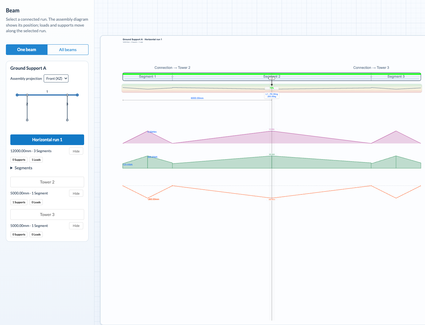
If No beams available appears, the current drawing contains no structural beams that the renderer can display. Check the drawing structures and the current calculation.
Straight segments connected at their endpoints appear as one continuous truss run with a shared origin. A support or an attached tower does not interrupt this run. Corners, towers, and branches remain separate selectable runs. Assemblies that have the same name or are spatially close but are separate in the structural model are not combined.
For assemblies with multiple runs, Assembly projection shows their positions. Select Front (XZ), Side (YZ), or Plan (XY) to identify spatial structures as well. Click a run in the overview or its entry below it. The selected run is highlighted. The projection view alone does not confirm a structurally effective connection; the detected structural model remains authoritative.
In the large beam diagram, segment boundaries mark the original components. Connection lists attached runs. Open Segments for the selected entry to see the segment ranges from the shared run origin. A segment button selects the corresponding drawing object. An object may contain multiple structural segments. The selection is retained when switching to the spatial view.
Ground Support Attachments are shown with a support symbol; rope suspensions retain their hoist symbol. Supports and loads are assigned to the appropriate run. For an object with multiple support points, individual points may belong to different runs. Moving a point still moves the entire drawing object.
Beam View is connected to the structural beams and their associated objects in the current drawing. It does not create a detached copy: the displayed supports and loads remain drawing objects. When you drag a load or support point along a beam, Production Assist updates its position in the drawing and refreshes the view.
You can also create a parametric structural truss run, actual PA point loads, cable supports, and hoist symbol instances in Truss Builder. There you can set a load's mass and edit its position by dragging or by setting its distance from the fixed start. Cable supports and hoists are separate PA drawing objects linked to the run. To add a hoist, select an imported symbol with cable-support geometry and click or tap the run. The symbol instance is aligned using its actual connection point; its reusable definition remains unchanged.
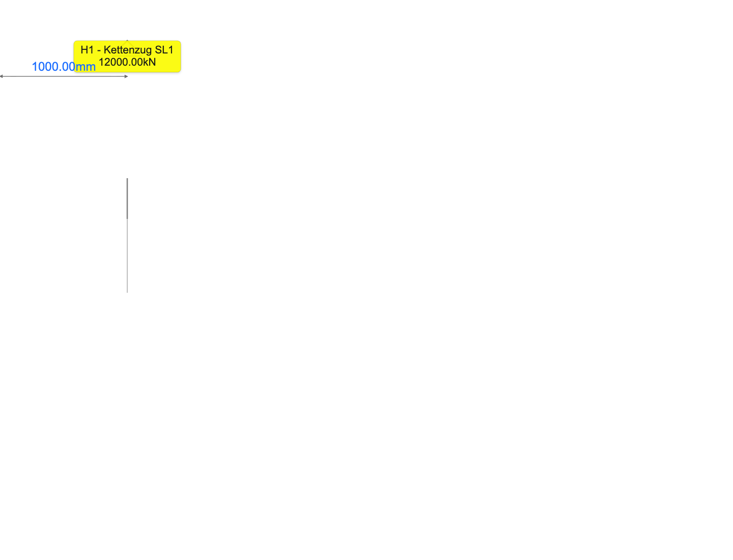
The diagram labels each hoist's distance from the fixed start and the overall span. Select a hoist or cable support in the diagram to move or delete it. The fields open next to the selected item. For hoists, you can also edit capacity and roof connection there. New hoists are initially created as held by the roof; the Upper attachment is restrained setting shows and changes this modeling assumption. After a current calculation, the Builder shows the selected hoist’s reaction and, when capacity is known, its utilization. The Inspector also shows the highest utilization calculated by Core for the selected run when matching current result values can be assigned. Otherwise, the value is marked unavailable; outdated results are not shown after a change. View force and deflection results opens the existing result view for the selected run with available section-force and deflection curves. After a change, the command remains disabled until another calculation is performed. Under Drawing diagnostics, the Builder shows messages for the active drawing. They are not limited to the selected run. An empty message area does not confirm that all checks passed. Shortening that would move a load, hoist, or cable support object past the new end is rejected; move the item first. Use the standard PA properties and calculation views for other structural and support values.
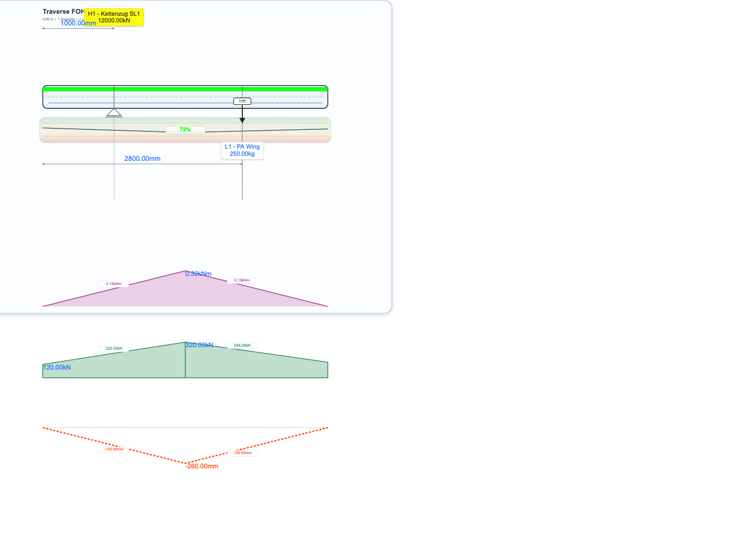
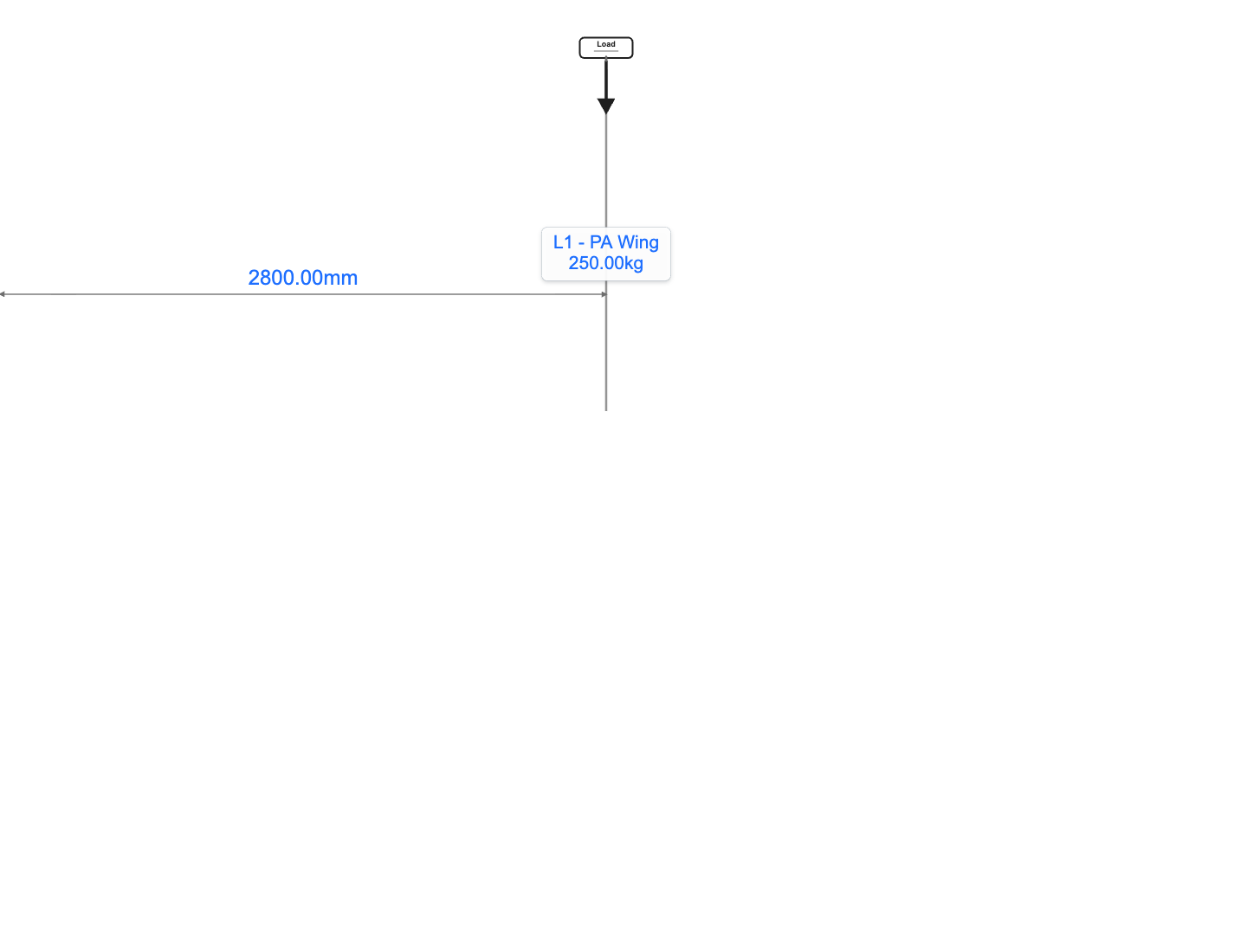
The individual views show how loads and supports are displayed along the beam, with their distances and labels.
After a structural calculation, Beam View can display the calculated curves along the beam. The examples show bending moment in pink, shear force in green, and deflection in blue. Labels mark calculated values at selected points. Deflection labels use the unit set under Unit for Dimensions in Print. Choose which result types appear in the renderer under Section Reactions in Navigation. The curves are not shown when the corresponding calculation results are unavailable.
Combined segments share a plot scale, so equal result values have equal plotted heights regardless of their original scales. Result curves remain separate for each calculation segment. Jumps at segment boundaries are preserved; values are not added for missing results. Reversed segments are converted to the shared run axes and common section direction. A vertical run starts at the bottom; other runs follow the positive first significant world coordinate, X, Y, or Z. The selected run is retained during a refresh as long as it still exists.
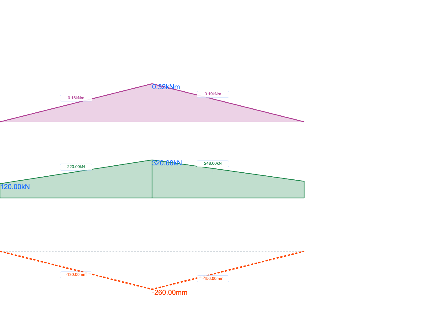
Beam View makes it easier to inspect an individual structure: the beam line, support and load positions, and calculation results are arranged in a 2D view. Use One beam to inspect a member or move an object along it. Use All beams for an overview of the beams in a drawing, and hide individual entries as needed.
For more information about selecting a view mode, see Renderer. For information about displaying and selecting calculation results, see Influence Lines.
For the corresponding overview with dimensions and editing parts of rigging structures, see Bridle View.