
🇬🇧

Documentation

Glossary

Electrical View: Using the Wiring Diagram#

The Electrical View is the Electrical tab under Window → Wiring. It displays power sources, distributors, consumers, and their power connections in an interactive diagram. Use it to check existing wiring, connect free ports, edit connections, arrange the diagram, and export a view.

This guide covers the electrical diagram. For manual and automatic patching in Object Properties or with Power Patch, see Electrical Planning. The Data tab is covered in Network Planning.

Prerequisites#

The drawing should contain the electrical objects you want to inspect or connect. For an object to appear in the diagram as a power source, distributor, or consumer, its symbol definition must have the corresponding electrical ports. A connection in the diagram is possible only when the selected ports are compatible according to the connection logic.

Open and read the electrical diagram#

  1. Open Window → Wiring.
  2. Select the Electrical tab.
  3. Find the devices in the diagram. Nodes show device names, object IDs, and power ports. Depending on the object, they may also show power and phase values.
  4. Follow the connection lines from a power source through distributors to consumers. Check utilization values in Object Properties as well; the diagram does not replace checking the entered limits.

The interface screenshot shows a generator, a distributor, and two consumers with example connections. Names and power values are examples; the devices, ports, and positions in your drawing depend on the objects it contains.
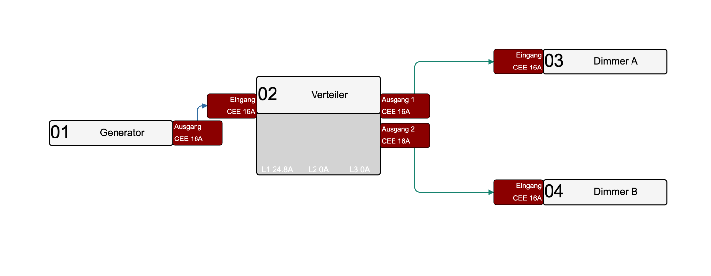
Electrical View showing a generator, a distributor, two consumers, connection nodes, and power connections

Check and edit connections#

Create a connection#

In the Electrical tab, drag from a node's port to a compatible port on another node. Then check that the connection line appears in the diagram and that the participating ports show the expected patch in Object Properties. The connection logic determines which port pairs are accepted.

The diagram is useful for checking and adding individual connections. To connect many devices systematically, use the manual or automatic patching workflows in Electrical Planning.

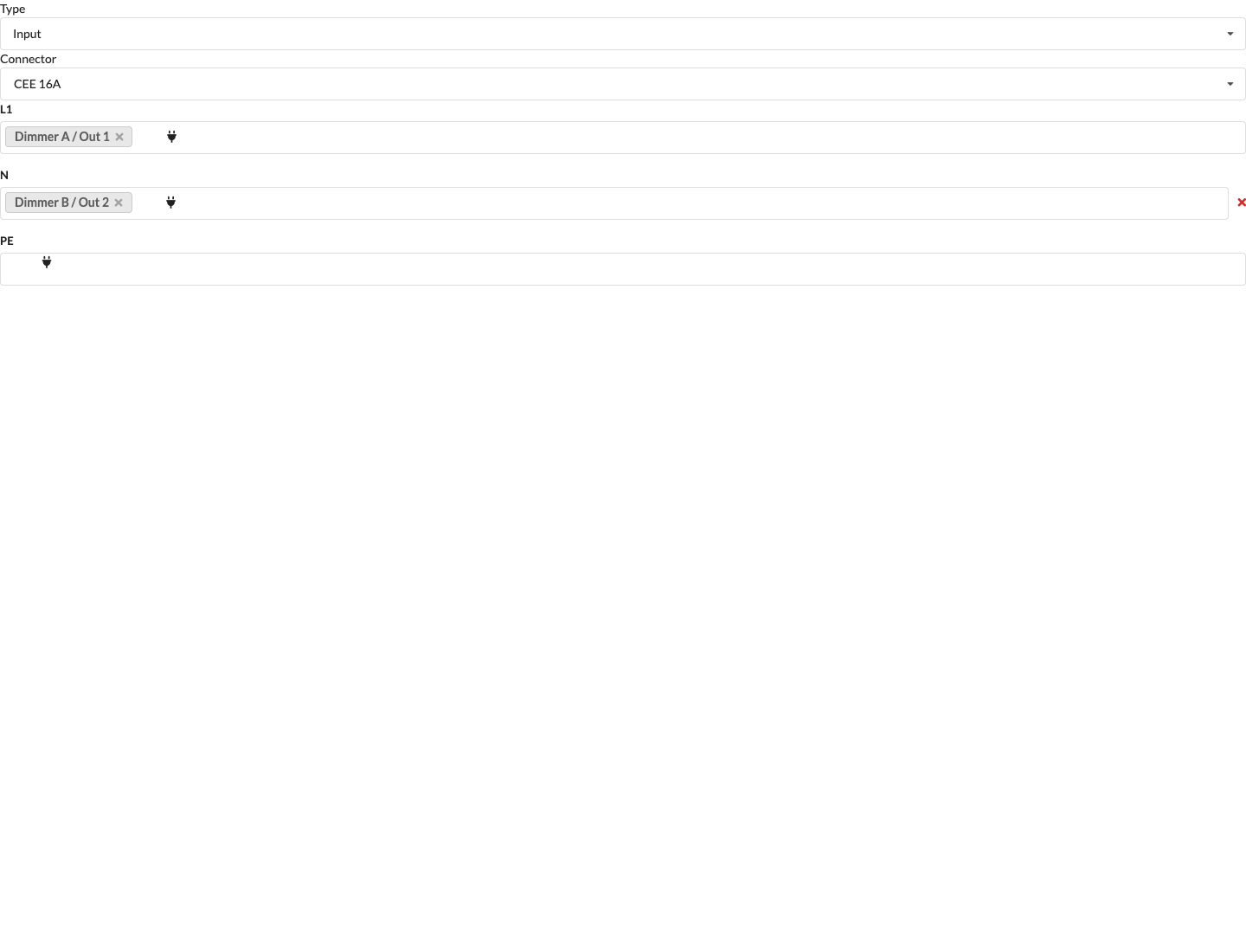
Electrical connection fields in Object Properties show patch assignments for each phase. Use this view to check the port patching of the devices involved.
Remove a connection or change its color#

  • Delete directly: Select the connection line and press Delete. This removes the selected connection immediately, without asking for confirmation.
  • Delete using connection details: Select the delete icon in the connection details. In the Do you want to delete the selected connection? dialog, select OK to delete it. Select Cancel, press Esc, click outside the dialog, or select its close icon to cancel.
  • Change the cable color: Select the color icon in the connection details to open the Choose a color for the cable color picker. Confirm the selected color with OK or discard it with Cancel.

Electrical Wire field in Object Properties showing example patch assignments on L1 and N

Arrange and filter the diagram#

  • Move nodes: Drag a node to the desired position. This changes only the diagram layout.
  • Reorder Tree: Resets the node positions.
  • Focus View: Fits the visible diagram area to its contents.
  • Filters: Select the filter icon to toggle Show only selected, Show Consumers, Show Unconnected, and Show Unconnectable. Color Connectors by Type and Show Utilization control how connections are displayed; Show Fuses toggles fuse visibility. A filter changes what is visible or how it is displayed, not the connections themselves.
  • Show Object Info: Displays Object Properties beside the diagram.

If an expected device is missing, check the filters and confirm that the object has suitable electrical ports.

Group nodes in the diagram#

  1. Select at least two nodes.
  2. Select Wrap Selected Nodes. The nodes are collected into a diagram group.
  3. Select the group name to open Wrapper Settings. Change Name and select OK. Select Cancel to discard the change.
  4. Use the color icon to set a group color. Confirm the color with OK or discard it with Cancel.
  5. Expand or collapse the group with + or −. Select Unwrap Selected Nodes to release the selected nodes from their diagram group.

The X in the group header opens Do you want to delete the group?. Select OK to remove the diagram group and release its objects. The objects and electrical connections remain. Select Cancel, press Esc, click outside the dialog, or select its close icon to cancel.

Diagram groups are only for organizing the Electrical View. They do not change an Assembly Group in the Scene Tree.
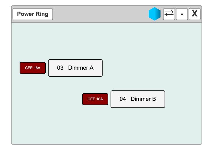
Electrical View group with two device nodes and color, reorder, collapse, and delete controls

  1. Arrange the diagram and open the Electrical tab you want to print.
  2. Select Print. Wait for the preview to finish loading. OK is disabled while it loads or when no image has been generated.
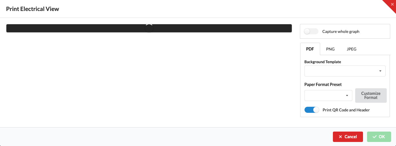
  3. Select PDF, PNG, or JPEG. Capture whole graph switches between the entire diagram and the visible area.
  4. Set the available options for the selected format and select OK. Select Cancel to close the dialog without exporting.

Print dialog for the electrical view with PDF, PNG, and JPEG options

For PDF, you can select a Background Template, a Paper Format Preset, and Print QR Code and Header. A usable QR link to the drawing requires an online project and suitable access rights. Custom PDF Format Settings opens the Custom PDF Format Settings dialog. There you can select a Paper Template and adjust Margin Left, Margin Right, Margin Top, Margin Bottom, Height, Width, Pagenumber Offset X, and Pagenumber Offset Y. Format Definition and Table Definition provide further settings. Use Update Preset, Create Preset, and Set as Default to manage the preset.

For PNG and JPEG, set Image Scale, Image Width, and Image Height; Max uses the largest possible size. For JPEG, you can also adjust the Resolution. The export uses the currently open tab. To print a data diagram, select Data first. See Network Planning for details.