

Production Assist is also available for AutoCAD and BricsCAD. These integrate directly into AutoCAD and BricsCAD and offer the same range of functions as the desktop app or all other plugins.
The user interface of the Production Assist Desktop can be connected to AutoCAD/BricsCAD.
Production Assist has the same range of functions and operation in AutoCAD and BricsCAD. For ease of reading, we always refer to AutoCAD here. BricsCAD and AutoCAD are always meant.
Production Assist works with:
(Mac & Windows)
Note: In BricsCAD for Mac, real-time integration only works after changing the view.
Note: In BricsCAD for Windows, for the changes in the Production Assist Desktop to be visible in BricsCAD, you must have the BricsCAD application in the foreground.
Attention: In order for Production Assist to work properly, both the desktop and the plugin must be installed. All support files such as cross sections and templates come with the installation.
There are two installation options:
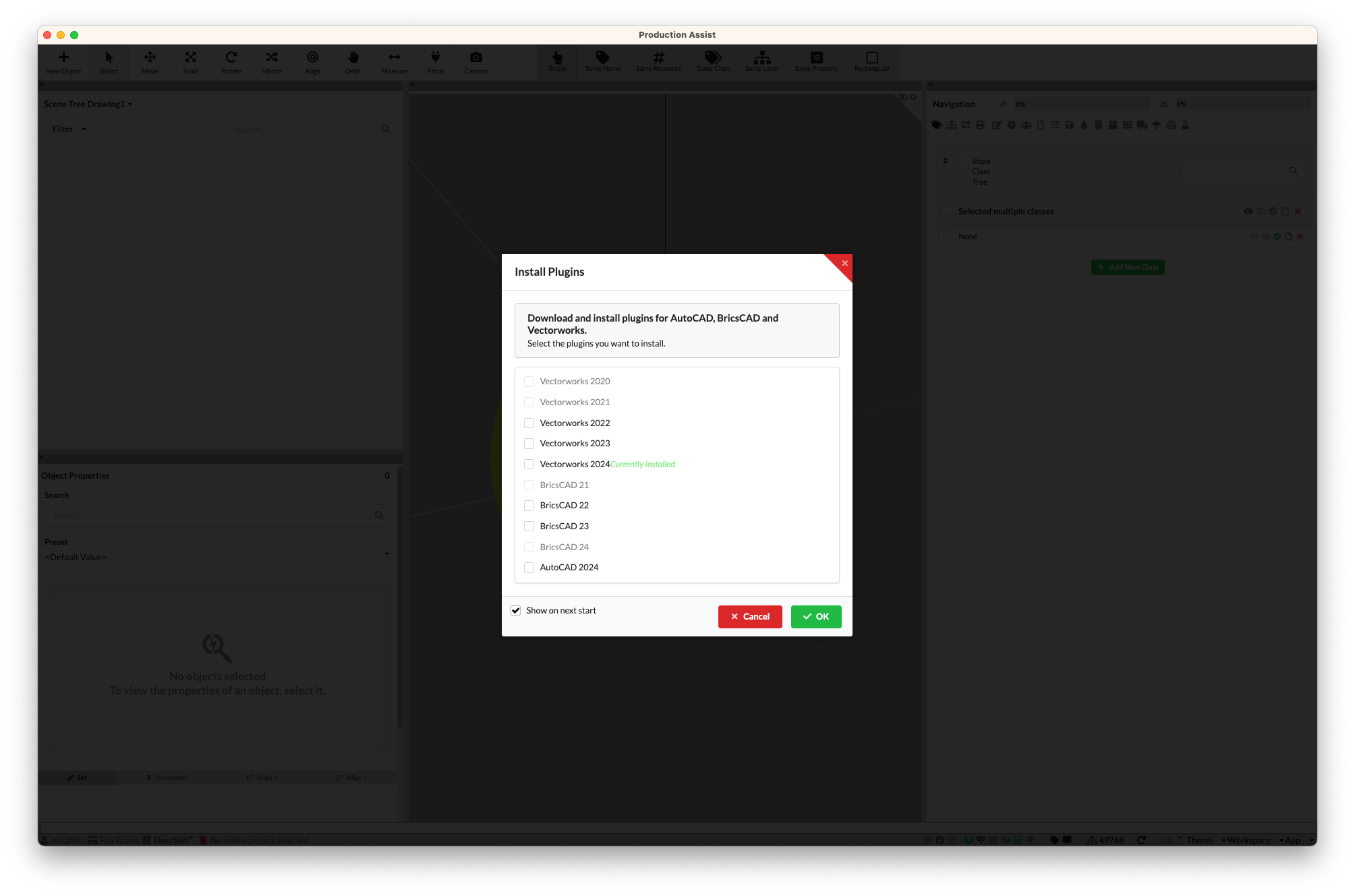
First install the Production Assist Desktop App. Start this and run the Menu Command Hilfe->AutoCAD-Plugin installieren... `.

This opens a dialog in which you can select the plugins that can be installed. Only plugins where the host application is installed can be installed. For example, if AutoCAD 2024 is not installed, the plugin cannot be installed either.
Installing the plugins takes a few minutes depending on your internet connection. After successful installation, the plugin was saved in the following folder:
Windows: %appdata%/productionassist/vw_plugin/XXX Mac: /Users/BENUTZERNAME/Library/Application Support/productionassist/vw_plugin/XXX
XXX stands for the version that is installed:
| Key | Application |
|---|---|
| BRX21 | BricsCAD 21 |
| BRX22 | BricsCAD 22 |
| BRX23 | BricsCAD 23 |
| BRX24 | BricsCAD 24 |
| BRX25 | BricsCAD 25 |
| BRX26 | BricsCAD 26 |
| ARX24 | AutoCAD 2024 |
| ARX26 | AutoCAD 2026 |
The advantage of installing via app is that Production Assist is automatically kept up to date.
Download the ZIP file for AutoCAD BricsCAD from the website and extract it. The ZIP file contains several folders. Each of these folders contains the files for the respective application.

The following assignment applies:
| Key | Application |
|---|---|
| BRX21 | BricsCAD 21 |
| BRX22 | BricsCAD 22 |
| BRX23 | BricsCAD 23 |
| BRX24 | BricsCAD 24 |
| BRX25 | BricsCAD 25 |
| BRX26 | BricsCAD 26 |
| ARX24 | AutoCAD 2024 |
| ARX26 | AutoCAD 2026 |
Installation for Windows
To use the files in the application, simply copy them to the AutoCAD Applications folder.

Installation for Mac
To use the files in the application, simply copy them to your user folder.
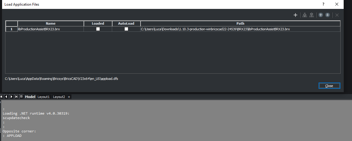
In order for Production Assist to be used in AutoCAD, it must be loaded using the APPLOAD command.
To do this, simply enter APPLOAD in the command line. The following dialog appears:
| BricsCAD | AutoCAD |
|---|---|
 | BricsCAD 21 |
Note If
Autoloadis selected, Production Assist will always automatically start with AutoCAD. Otherwise, anAPPLOADmust always be carried out manually.
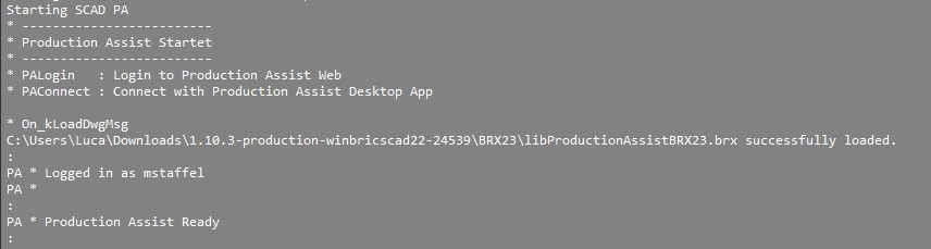
If the plugin has been loaded successfully, the following text will be displayed in the command line.
| BricsCAD | AutoCAD |
|---|---|
 | BricsCAD 21 |
In order to connect the desktop app to AutoCAD, the plugin mode, which is located at the bottom right of the footer, must be activated.

This automatically connects to the running AutoCAD instance.

In order for Production Assist to read the drawing from AutoCAD, the blocks must be prepared.
This can either be done via:
The advantage of the Symbol Map is that it works with all blocks and therefore without having to adapt them. You can map each block to a Production Assist symbol and start quickly. The disadvantage is that you can only map blocks for which there is an equivalent of Production Assist blocks. You can also create these yourself.
The advantage of layer integration is that there is more flexibility in creating blocks and you do not have to create Production Assist symbols beforehand or maintain their rotation. The disadvantage is that you have to adapt your own blocks in advance. But this only has to happen once.
When defining the structure using lines, you can easily define the structural members using AutoCAD lines and curves. This allows for the greatest possible flexibility when creating content.
In order for the lines to be recognized by Production Assist, they must be drawn on previously defined layers.
The names of the layers can be freely chosen. To do this, go to File->Settings . Select the Structure properties in the panel on the left.

| Field | Description |
|---|---|
| Layer / Class Name | Defines the name of the layer in AutoCAD on which all lines are read as structures. |
| Layer Cross Section | Defines the cross section used for the structure. |
| Internal structure | Defines whether the structure should be calculated as an internal structure. This is used, for example, to enable a separate calculation of trusses and center lines for trusses. |
To add a new layer, you can simply enter it below the table. When the Add Layer / Class button is clicked, a new entry is added to the table. This can then be adjusted.
Note All AutoCAD lines and curves can be created as structural elements.
In order for Production Assist to process the lines correctly, they must follow certain rules. These are shown in the following table:
| OK | Description | Not OK |
|---|---|---|
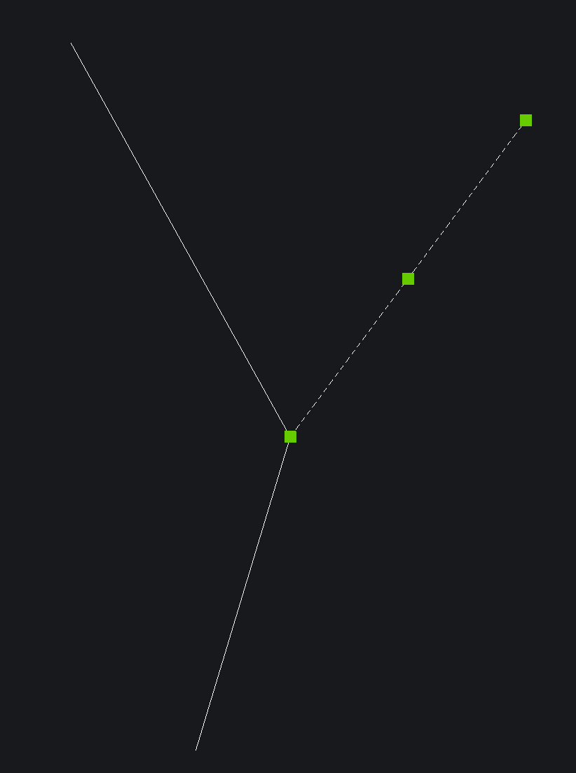 | The end points of the lines must lie exactly on the other line or the other end points of connected lines. Otherwise the structural elements cannot be connected to each other properly. | 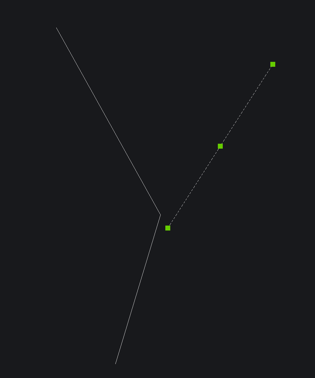 |
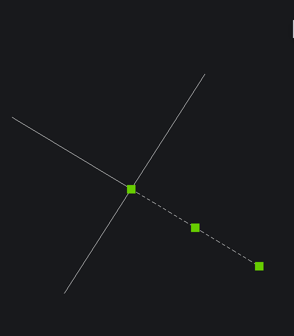 | Crossing lines are not automatically connected. To connect the lines together, one of the lines must end on the other. | 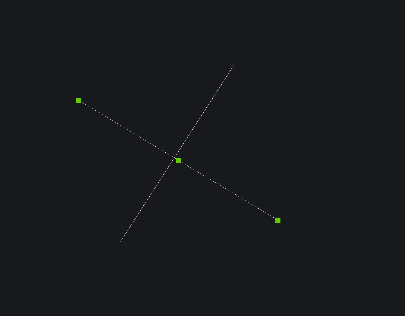 |
Supports can also be defined this way. For this purpose, points on named layers are used. The setting can be made in the same dialog as the lines.
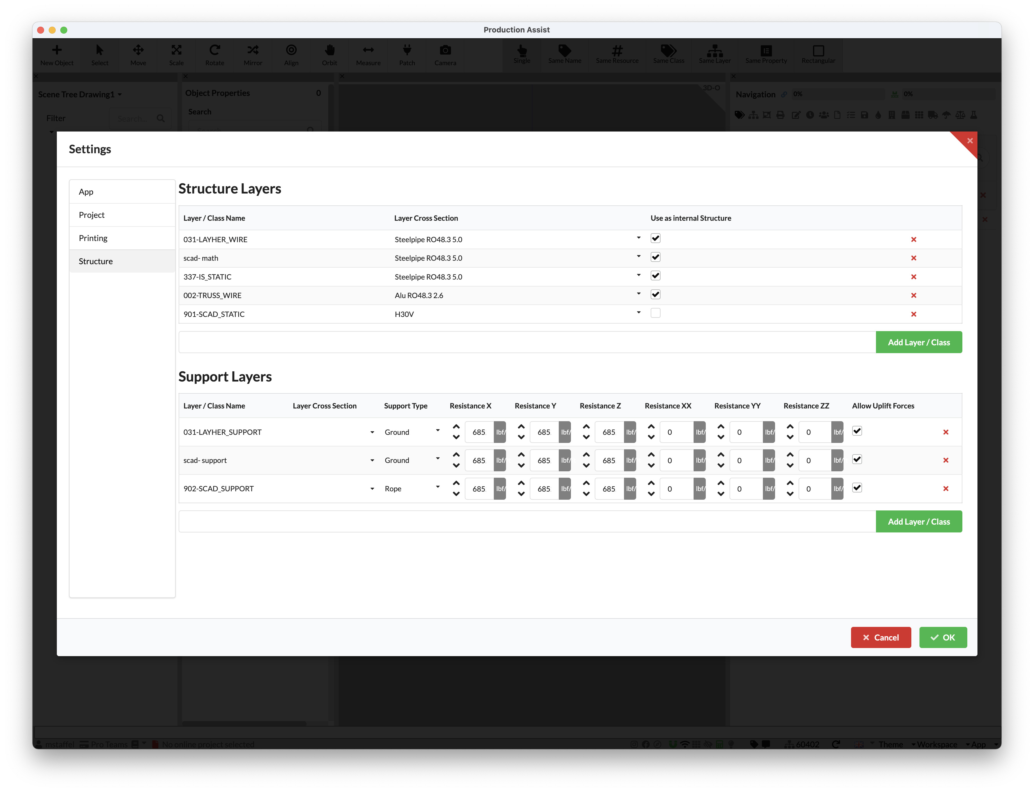
| Field | Description |
|---|---|
| Layer / Class Name | Defines the name of the layer in AutoCAD on which all points are read as supports |
| Layer Cross Section | Only for rope supports: Defines the cross section which the rope is using. If no cross-section is entered, the rope is assumed to be inextensible. |
| Support Type | Defines the support type: There are Rope for rope supports and Ground for ground supports |
| Reaction X | Only for ground supports: Defines the spring value for the support in the respective direction. |
| Allow Uplift Forces | Only for ground supports: Defines whether the support allows uplifting forces. |
The easiest way to read the current blocks of a drawing from AutoCAD is via the command File->AutoCAD Integration->Prepare Symbol for Production Assist .
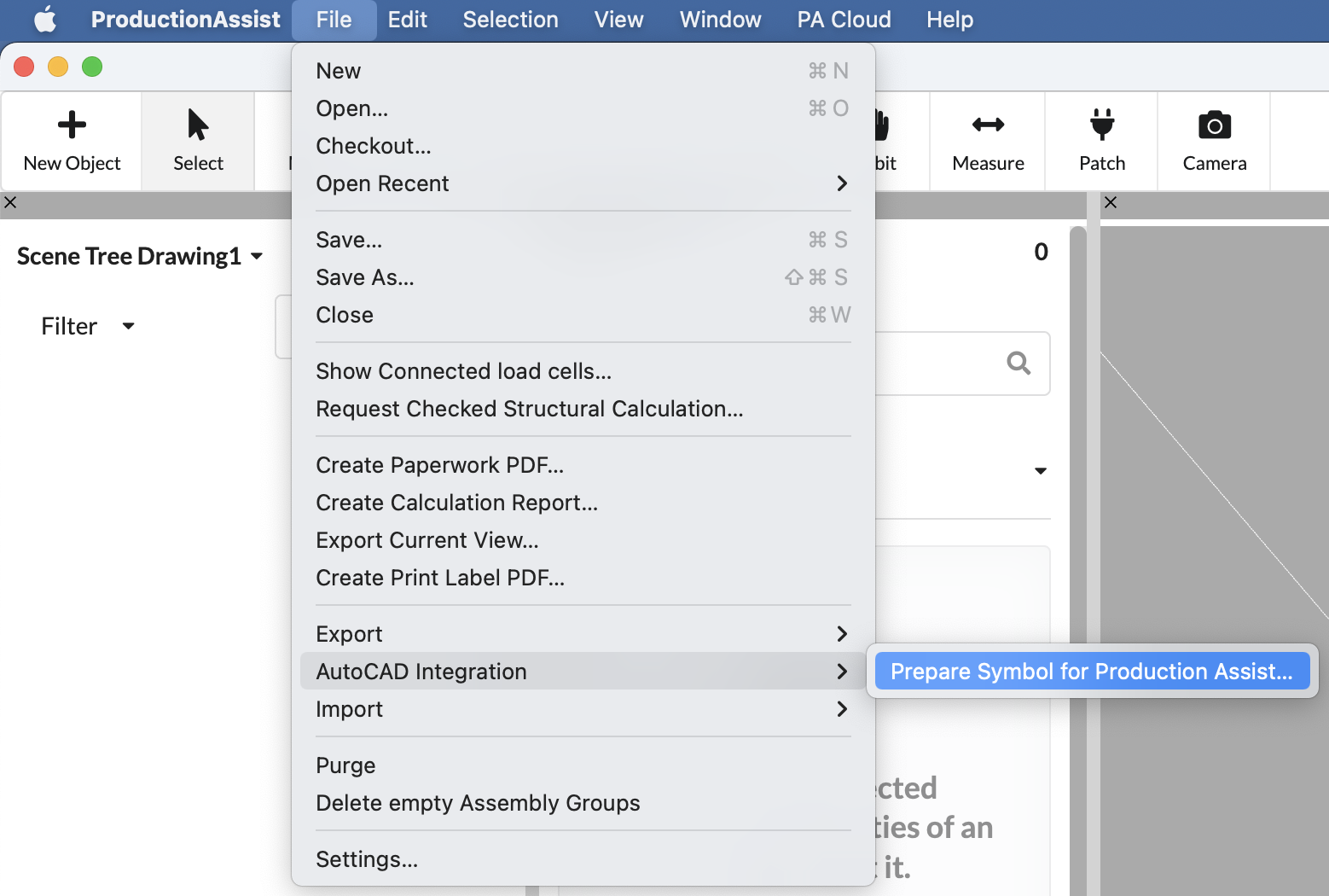
A dialog opens in which all blocks of the drawing are listed. These can now be assigned to Production Assist symbols.

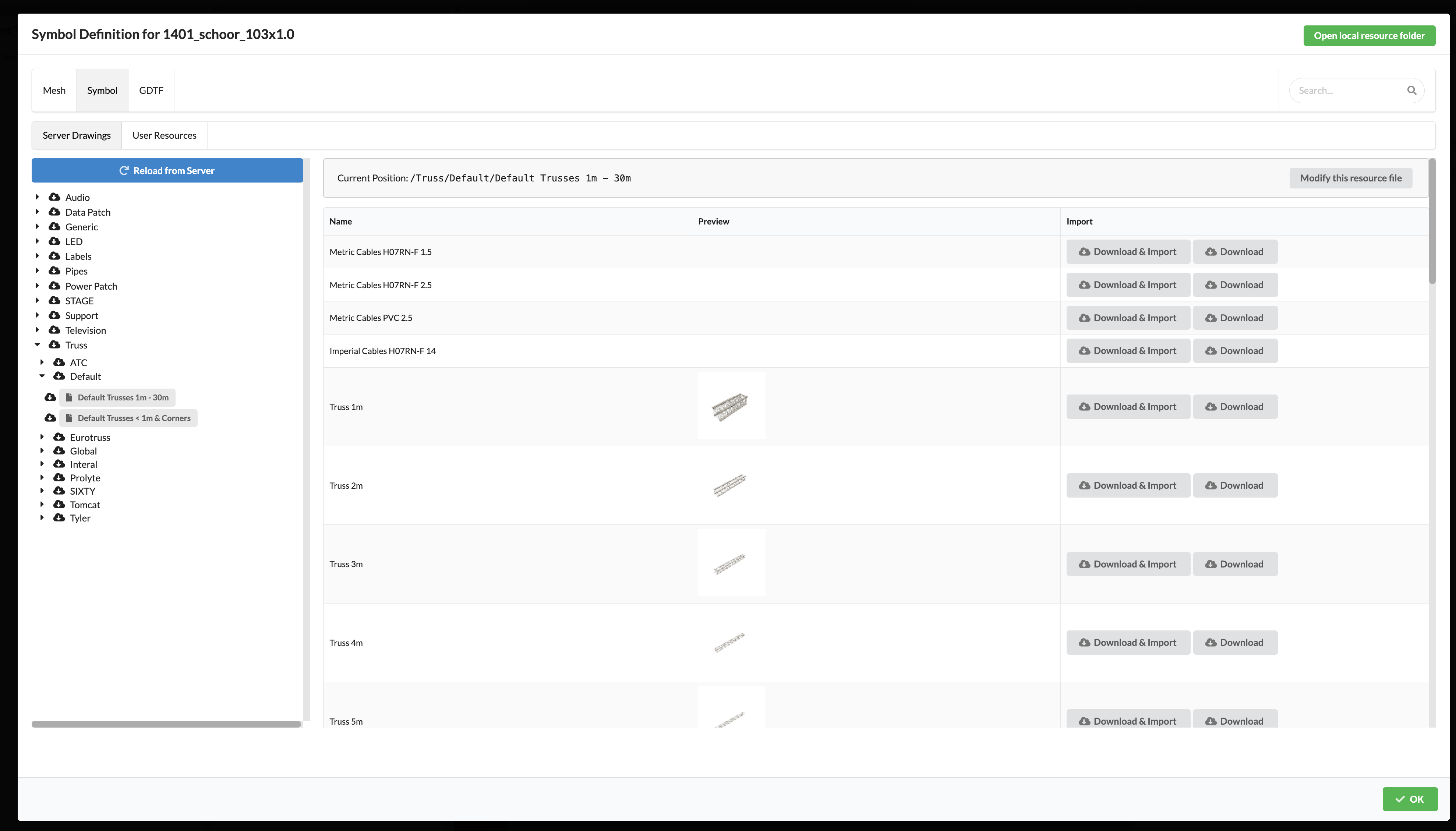
To do this, press Edit and the Production Assist symbol selector opens.
Select the symbol that matches the block.
Attention: The orientation of the block and the Production Assist symbol must be the same.
The mapping is saved in the symbol map. This is stored in the Resource Manager.
| Symbol Map | Resource Manager |
|---|---|
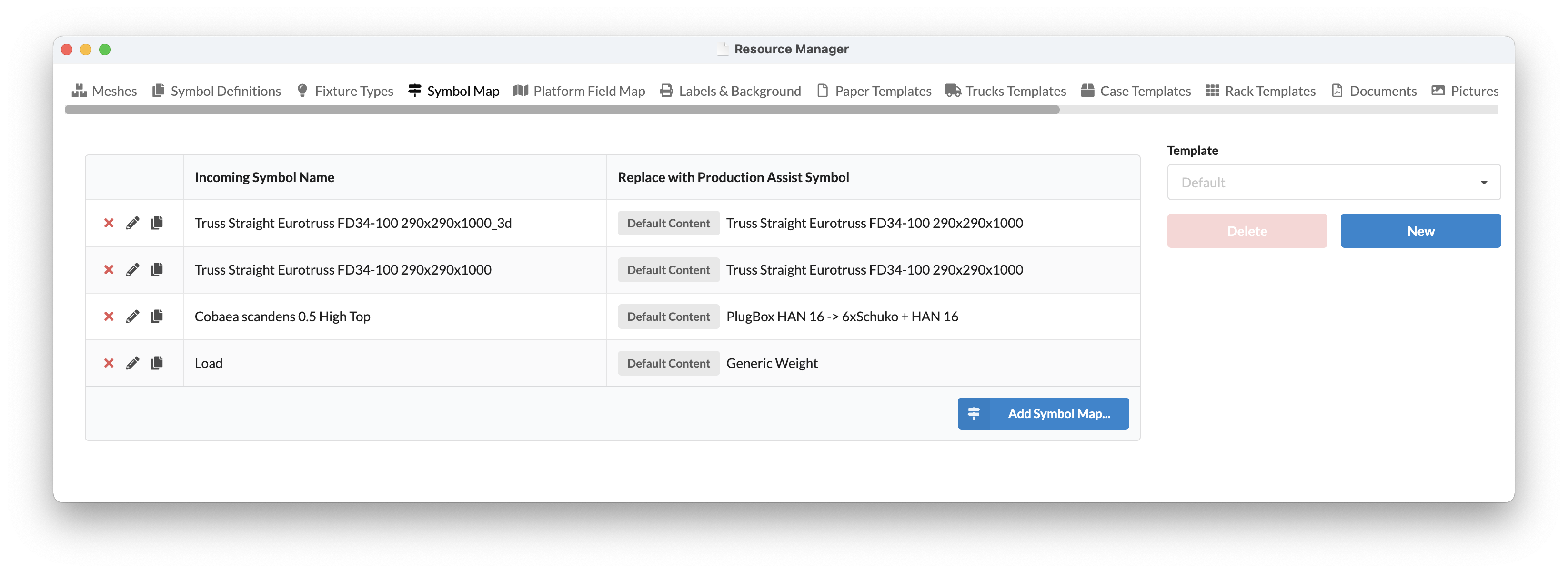 | 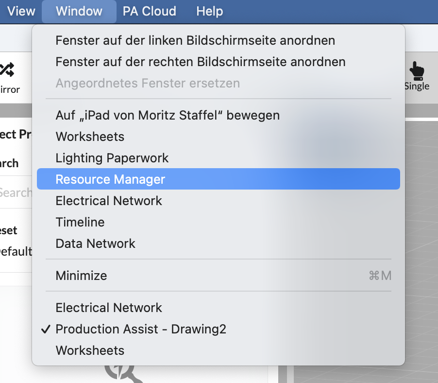 |
To display properties in AutoCAD, you can connect attributes from AutoCAD to Production Assist. This is done via the Field Map.
The Field Map can be found under Window -> Resource Manager.
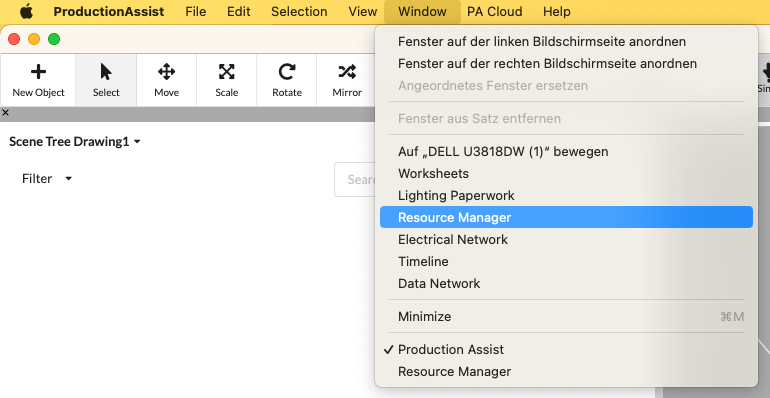
Now click on the Field Map tab.
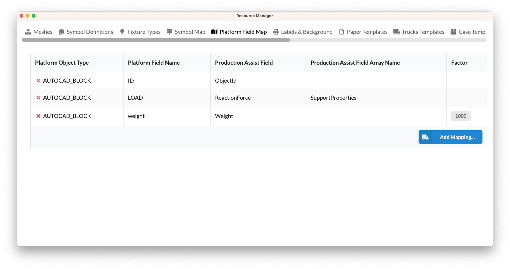
| Field | Description |
|---|---|
| Platform object name | Describes the name of the database of the respective platform. For AutoCAD this is AUTOCAD_BLOCK . |
| Properties Platform name | Describes the name of the attribute that is to be mapped. Upper and lower case letters must be observed. |
| Production Assist Properties Name | The mapped Universal Production Assist name of the property |
| Production Assist Properties Array Name | The mapped universal Production Assist name of the property if it comes from an array property. |
| Factor | The factor by which you have to divide the AutoCAD value to get the Production Assist unit. |
Note Production Assist uses the SI Compliance as base units. For example, this is grams for weight. To map from an attribute that is defined in kilos, you need a factor.
The following units are used as basic units in Production Assist:
| Field | Description |
|---|---|
| Weight | Gramm |
| Length | Millimeter |
| Force | Kilonewton |
Example 1: The weight of an object should be linked to an attribute in AutoCAD. In AutoCAD the weight should be displayed in kilos. To do this, the factor
0.001must be entered. 1 kilogram * 0.001 = 1 gram
Example 2 The weight of an object should be linked to an attribute in AutoCAD. In AutoCAD you want the weight to be displayed in pounds. To do this, the factor
0.00220462must be entered. 1 pound * 0.00220462 = 1 gram
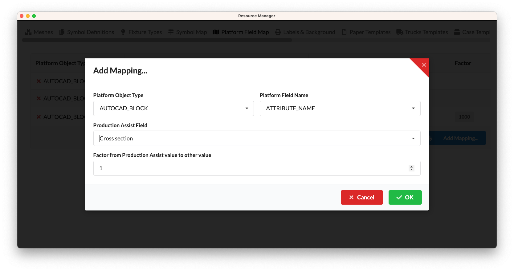
To add your own mapping, simply click Add Mapping...
The calculation results in AutoCAD are automatically inserted into specific layers.
These always contain the prefix ProductionAssist__ and then the value that they represent.
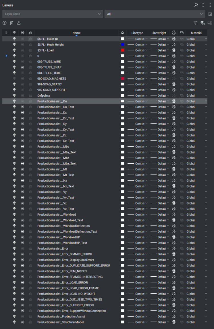
| Layer Name | Description |
|---|---|
| ProductionAssist__Du | Displays the combined deflection figure. This is the vector addition of Dx, Dy and Dz. |
| ProductionAssist__Dx | Shows the deflection in the X direction |
| ProductionAssist__Dx_Text | Shows the local maxima of the deflection in the X direction |
| ProductionAssist__Dy | Shows the local maxima of the deflection in the Y direction |
| ProductionAssist__Dy_Text | Shows the deformation in Y direction |
| ProductionAssist__Dz | Shows the local maxima of the deflection in the Z direction |
| ProductionAssist__Dz_Text | Shows the local maxima of the deflection in the Z direction |
| ProductionAssist__Nx | Shows the normal force in the X direction |
| ProductionAssist__Nx_Text | Shows the local maxima of the normal force in the X direction |
| ProductionAssist__Vy | Shows the shear force in Y direction |
| ProductionAssist__Vy_Text | Shows the local maxima of the shear force in the Y direction |
| ProductionAssist__Vz | Shows the shear force in the Z direction |
| ProductionAssist__Vz_Text | Shows the local maxima of the shear force in the Z direction |
| ProductionAssist__Mt | Displays the torsion around the X axis |
| ProductionAssist__Mt_Text | Shows the local maxima of the torsion around the X axis |
| ProductionAssist__Mby | Displays the bend around the Y axis |
| ProductionAssist__Mby_Text | Shows the local maxima of the bend around the Y axis |
| ProductionAssist__Mbz | Displays the bend around the Z axis |
| ProductionAssist__Mbz_Text | Shows the local maxima of the shear force in the Z direction |
| ProductionAssist__Workload | Shows the workload on the structural element |
| ProductionAssist__Workload_Text | Shows the local maxima of the workload on the structural member |
| ProductionAssist_Errors | Displays error messages |